


Adding the tunnel interfaces to the VPN
- On External, go to Policy & Objects > Addresses and create an address for the External tunnel interface.
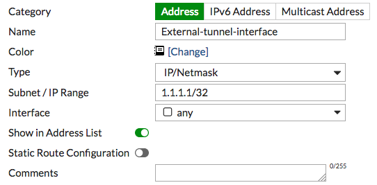
- Create a second address for the Branch tunnel interface.
For this address, enable Static Route Configuration.

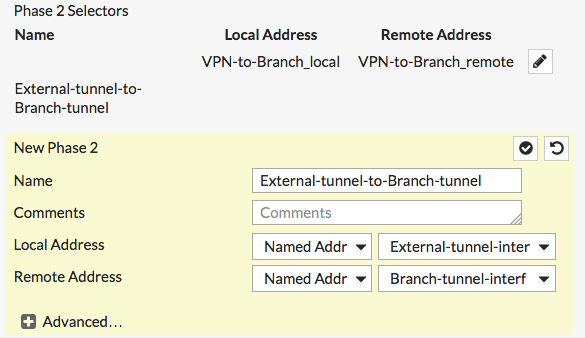
- Go to VPN > IPsec Tunnels and edit the VPN tunnel.
Select Convert To Custom Tunnel.
Under Phase 2 Selectors, create a second Phase 2 allowing traffic between the External tunnel interface and the Branch tunnel interface.
- Go to Network > Static Routes and create a route to the Branch tunnel interface.
Set Destination to Named Address and select the firewall address.
Set Device to the tunnel interface.

- Go to Policy & Objects > IPv4 Policy and edit the policy allowing local VPN traffic.
Set Source to include the External tunnel interface.
Set Destination to include the Branch tunnel interface.

- Edit the policy allowing remote VPN traffic to include the tunnel interfaces.

On Branch, repeat this procedure to include the following:
- Addresses for both tunnel interfaces. You must enable Static Route Configuration for the Branch tunnel interface.
- A Phase 2 allowing traffic between the Branch tunnel interface and the External tunnel interface.
- A static route to the External tunnel interface.
- Edited policies that allow traffic to flow between the tunnel interfaces.
- Go to Monitor > IPsec Monitor and restart the VPN tunnel to implement the new phase 2.