Overview
FortiWeb-VM HA (High Availability) Cluster can be deployed on Google Cloud through Terraform. In this document we assume FortiWeb's operation mode is Reverse Proxy.
FortiWeb HA on Google Cloud supports active-passive HA and high volume active-active HA. For information on the HA modes, see FortiWeb high availability (HA) in FortiWeb Administration Guide.
In high volume active-active HA modes, all the instances in the HA group process traffic. We use load balancer to distributes traffic to all the HA members. If an instance is down, it will be ignored by the load balancer for traffic distribution. If the failed instances is the Primary node, one of the Secondary instances immediately takes its role to become the new Primary.
In active-passive mode, only the Primary instance processes traffic. The load balancer forwards traffic to the Primary node. When the Primary node fails, the Secondary immediately takes the Primary role and processes traffic forwarded from the load balancer.
The following resources will be created in the deployment process:
-
A load balancer with public IP address.
-
FortiWeb-VM instances. The VMs are added in the load balancer's backend pool. We support up to eight FortiWeb-VMs in an HA group on Google Cloud.
Note the Google Cloud HA deploy script only supports two FortiWeb VM devices for quick deploy
-
A public facing subnet connecting the FortiWeb outgoing interface (port1) to the load balancer.
-
A private subnet where one or more web application VMs that FortiWeb protects are located.
-
A private subnet which contains HA heartbeat interfaces .
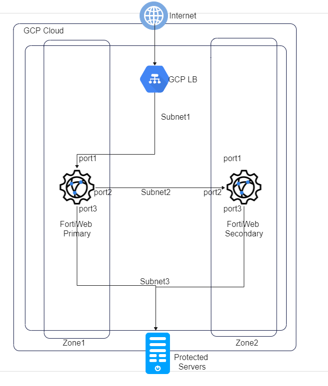
All the web traffic passes through the load balancer first, then it is directed to a collection of VMs called a backend pool. On public cloud platform, configurations are synchronized through FortiWeb's HA feature, but the traffic distribution among HA cluster members is achieved by the load balancer instead, so FortiWeb-VM itself doesn't set up traffic group and node allocation.
The following graph shows a typical active-passive HA topology.