


Mapping the virtual NICs (vNICs) to physical NICs
Appropriate mappings of the FortiWeb-VM network adapter ports to the host computer’s physical ports depends on your existing virtual environment.
|
|
Often, the default bridging vNICs work, and don’t need to be changed. If you are unsure of your network mappings, try bridging first before non-default vNIC modes such as NAT or host-only networks. The default bridging vNIC mappings are appropriate where each of the host’s guest virtual machines should have their own IP addresses on your network. The most common exceptions to this rule are for VLANs and the transparent modes. See Configuring the vNetwork for the transparent modes. |
When you deploy the FortiWeb-VM package, 4 bridging vNICs are created and automatically mapped to a port group on 1 virtual switch (vSwitch) within the hypervisor. Each of those vNICs can be used by one of the 4 network interfaces in FortiWeb-VM. (Alternatively, if you prefer, some or all of the network interfaces may be configured to use the same vNIC.) vSwitches are themselves mapped to physical ports on the server.
You can change the mapping, or map other vNICs, if either your VM environment requires it or the FortiWeb-VM will be operating in either true transparent proxy or Transparent Inspection mode. (For information on how to choose the operation mode, see the setup instructions in the FortiWeb Administration Guide.)
The following table provides an example of how vNICs could be mapped to the physical network ports on a server.

Example: Network mapping for Reverse Proxy mode
To map network adapters
- On your management computer, start Citrix XenCenter.

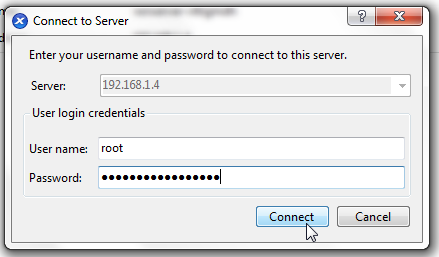
- In the pane on the left side, double-click the name of the XenServer. This will open an authentication dialog.
- In Server, type the IP address or FQDN of the Citrix XenServer server.
In User name, type the name of your account on that server.
In Password, type the password for your account on that server.
Click Connect.
- In the pane on the right side, click the Networking tab, then click Add Network.
- In the list of virtual hardware on the left side of the dialog, click the name of a virtual network adapter to see its current settings.

- From the Network Connection drop-down menu, select the virtual network mapping for the virtual network adapter.

- Click OK.
- Continue with Powering on and shutting down the virtual appliance.
The hypervisor’s networking dialog appears.
The correct mapping varies by your virtual environment’s network configuration. In the example illustration below, the vNIC is mapped to the virtual network (vNetwork) named Network 3.
Configuring the vNetwork for the transparent modes
The default vNetwork configuration does not function with FortiWeb bridges (V-zones). You use bridges when you deploy your FortiWeb-VM in either true transparent proxy or Transparent Inspection operation mode.
Use the following general configuration steps to support the transparent modes:
- Add 2 vSwitches or distributed vSwitches (dvSwitch) for the bridge: one for the web server side, and one for the client side
Alternatively, add a single vSwitch that provides two different VLAN IDs. Use these IDs to create VLAN subinterfaces to add to a bridge.
- Set both to promiscuous mode
- Set each vSwitch you add to promiscuous mode and map it to a network adapter (vNIC)
Similar to a deployment that does not use virtual machines, connections between clients and servers travel through the two vSwitches (or two VLANs) that comprise the bridge, with FortiWeb-VM in between them.
![]()
The following instructions assume your configuration uses 2 vSwitches.
To create a vSwitch
- On your management computer, start Citrix XenCenter.

- In the pane on the left side, double-click the name of the XenServer. This will open an authentication dialog.
- In Server, type the IP address or FQDN of the Citrix XenServer server.
In User name, type the name of your account on that server.
In Password, type the password for your account on that server.
Click Connect.

- In the pane on the left side, select either the name of a XenServer pool, or (if your web servers are on the same XenServer as FortiWeb-VM) a single XenServer.
- On the Configuration tab, click Networking.
- Depending on whether FortiWeb-VM will run transparently between clients and web servers on the same Xen server, select either:
vSwitches will allow communication between different Xen Servers in the same pool.
A window appears where you can configure single server vSwitches or (if you selected a pool in the previous step) distributed vSwitches.
-
Cross-Server Private Network — Select this option if your web servers are not hosted on the same Xen server as your FortiWeb-VM, but are in the same resource pool.
This option is greyed out and unavailable if you have not yet installed Citrix’s Distributed Virtual Switch Controller (Open vSwitch) or have software-defined networking (SDN) available. You must also add the XenServer to the dvSwitch; enter this command on the CLI of each XenServer, then reboot it:xe-switch-network-backend openvswitch
- Single Server Private Network — If your web servers are on the same Xen server as your FortiWeb-VM, you can select this option.
Client-Side-vSwitch1 that identifies the port group.To configure promiscuous mode for the new vSwitches
- Connect to the CLI of the XenServer where you are deploying FortiWeb-VM.
- To show the UUID of the vNetwork enter the command:
- Enter the command:
- To show the UUID of the virtual network interface, enter the command:
- Enter the command:
- Unplug and re-connect the virtual network interface by entering these commands:
- Repeat this procedure to configure the mode of the other, server-side vSwitch.
- Continue with To map a network adapter to the new vSwitches.
xe pif-list network-name-label="Client-Side-vSwitch1"
where Client-Side-vSwitch1 is the name of a network as it appears in XenCenter.
xe pif-param-set uuid="0" other-config:promiscuous="true"
where 0 is the UUID of the physical interface. If successful, the output of this command will verify that the physical interface is now in promiscuous mode:
xe pif-param-list uuid="0"
xe vif-list vm-name-label=FortiWeb-vm
where FortiWeb-vm is the name of the virtual machine as it appears in XenCenter.
xe vif-param-set uuid="0" other-config:promiscuous="true"
where 0 is the UUID of the virtual interface. If successful, the output of this command will verify that the virtual interface is now in promiscuous mode:
xe vif-param-list uuid="0"
xe vif-unplug uuid="0"
xe vif-plug uuid="0"
To map a network adapter to the new vSwitches
- In the pane on the left side, click the name of the virtual appliance, such as FortiWeb-VM.

- On the Networking tab, select a vNIC (Device), then click Properties.
- Select the new vSwitch from the Network drop-down list.
- Click OK.
- Repeat this procedure with the other vSwitch for the bridge.
- Later, when configuring FortiWeb-VM, add port2 and port3, or whichever FortiWeb ports correspond to the vSwitches you created in this procedure, to the bridge (V-zone).
A properties window appears.