
Fortinet white logo
Fortinet white logo

Administration Guide

Using clone pools

Using clone pools

A clone pool consists of a set of destination monitor servers. FortiADC protects real-server pools by duplicating incoming traffic and sending a copy to the clone pool, which retains it for monitoring purposes. The clone pool is assigned to a virtual server, and within this pool are a set of monitor servers, some of which may be IDS (Intrusion Detection System) servers. These IDS servers analyze the traffic to detect suspicious patterns but do not perform firewall functions, such as blocking traffic. Instead, the IDS servers may, for example, send notifications like an email when potential threats are detected.

Important: The clone pool receives the same traffic as the real-server pool, ensuring it mirrors the traffic for monitoring purposes.

To configure a clone pool, you first create a pool of IDS or sniffer devices and then assign the pool as a clone pool to a virtual server. The clone pool feature is the recommended method for copying production traffic to IDS systems or sniffer devices. Note that when you create the clone pool, the service port that you assign to each node is irrelevant; you can choose any service port. Also, when you add a clone pool to a virtual server, the system copies only new connections; existing connections are not copied.

You can configure a virtual server to copy client-side traffic, server-side traffic, or both:

  • A client-side clone pool causes the virtual server to replicate client-side traffic (prior to address translation) to the specified clone pool.
  • A server-side clone pool causes the virtual server to replicate server-side traffic (after address translation) to the specified clone pool.

Clone pool topology illustrates how clone pools work.
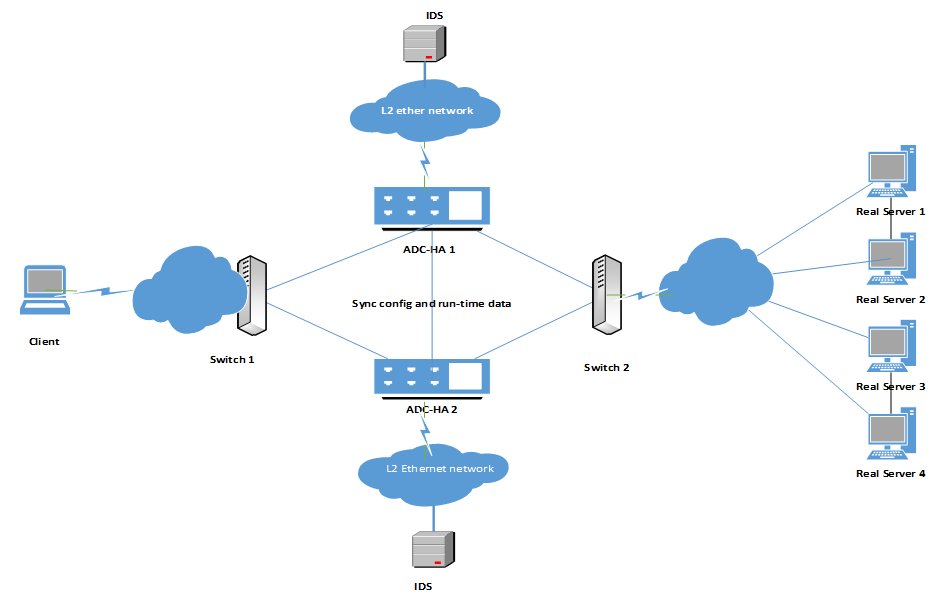
Clone pool topology

The following steps show the process in which FortiADC clones packets and sends them to the monitor servers:

  1. Duplicates the packet data structure.
  2. Looks up the route table by monitor server IP to find out the next-hop IP address and output device, if necessary.
  3. Looks up the neighbors by the next-hop IP address, if necessary.
  4. Updates packet headers with specified values or results of route and ARP look-up.
  5. Sends the packets out to the monitor servers.

Configuring a clone pool

Before starting to create clone pools, keep the following in mind:

  • Only one clone pool can be configured for the virtual server.
  • The clone pool can have at most four members. The traffic will be duplicated and sent to each of the members.
  • Only IPv4 addresses are supported.
  • There are four modes by which you may update and send the packets.
  • When the clone pool is added to the virtual server, the traffic (of old sessions and new) is duplicated and sent to the monitor servers in the clone pool.
  • The following is true:
    • If the virtual server is of the type L7, then the profiles TURBOHTTP, HTTP, HTTPS, TCPS, RDP, are supported.
    • If the virtual server is of the type L2, then the profiles TCP, UDP, IP, HTTP, HTTPS, TCPS, are supported.
    • If the virtual server is of the type L4, then the profiles TCP, UDP, FTP, are supported.
  • Traffic of both client and server sides may be cloned. For the client-side, traffic is replicated BEFORE the packet's address undergoes Network Address Translation (NAT) such that it may reach the clone members. For the server-side, however, NAT has already happened; the packet has already gone through the virtual server. Thus the traffic is replicated AFTER the packet address has been translated.

To configure a clone pool:

The following instructions assume that you have properly configured schedule groups, real servers, and real server pools.

  1. Go to Server Load Balance > Virtual Server.
  2. Click the Clone Pool tab.
  3. Click Create New to display the configuration editor.
  4. Enter a name for the configuration and click Save.
    Once the clone pool configuration is saved, the Pool Member section becomes configurable.
  5. Under the Pool Member section, click Create New to create a member inside your clone pool. You can create up to four members.
  6. Refer to the table below for entries and/or selections required for creating a clone pool.

Parameters for clone pool configuration

Entry/Selection Description

Clone Pool

Name

Specify a unique clone pool name

Pool Member

Name

Specify a unique pool member name.

Note: A pool member is a clone server. So this name is essentially the name you give to the clone server.

Interface

Select the interface (port) FortiADC uses to send out packets to the clone server.

Mode

The headers of duplicated packets need to be updated when sent to monitor servers. There are several modes in which this occurs. Select one of the following:

  • Mirror Interface—This mode does not change the packet header at all. It is most commonly used; with it, the monitor does not look at the content of the packet, neither does it receive the payload, it merely looks at how much data is being passed, and counts the bytes of the data. The original Layer 2 Destination Address (DA) or Source Address (SA) and Layer 3 IP Addresses are left intact. In this mode the FortiADC simply sends the packets "as is" out from the specified interface.
  • Mirror Destination MAC Address Update—This mode uses Layer 2 forwarding. With the incoming packet, the ADC replaces the destination MAC address with the specified destination MAC address. It is preferred when connecting the ADC to end devices like the IDS.
  • Mirror Source MAC Update—This mode replaces the source MAC address in the incoming packet with the specified MAC address on the FortiADC device. This option is recommended where not changing the source MAC address could cause a loop.
  • Mirror Source Destination MAC Update—This mode replaces both the source and destination MAC addresses at Layer 2, but does not change the Layer-3 IP addressing information.
  • Mirror IP Update—This mode replaces the incoming packet’s IP address with the specified IP address and then forwards the duplicated packet to those servers. This mode may also change the Layer 4 source and destination ports. If the virtual server port isn't set to wildcard port 0 while the port IS specified, the Layer 4 destination port on the duplicated packets will be changed to the specified value. This option is recommended for scenarios in which monitor servers are not directly connected to the ACOS device.

Using clone pools

Using clone pools

A clone pool consists of a set of destination monitor servers. FortiADC protects real-server pools by duplicating incoming traffic and sending a copy to the clone pool, which retains it for monitoring purposes. The clone pool is assigned to a virtual server, and within this pool are a set of monitor servers, some of which may be IDS (Intrusion Detection System) servers. These IDS servers analyze the traffic to detect suspicious patterns but do not perform firewall functions, such as blocking traffic. Instead, the IDS servers may, for example, send notifications like an email when potential threats are detected.

Important: The clone pool receives the same traffic as the real-server pool, ensuring it mirrors the traffic for monitoring purposes.

To configure a clone pool, you first create a pool of IDS or sniffer devices and then assign the pool as a clone pool to a virtual server. The clone pool feature is the recommended method for copying production traffic to IDS systems or sniffer devices. Note that when you create the clone pool, the service port that you assign to each node is irrelevant; you can choose any service port. Also, when you add a clone pool to a virtual server, the system copies only new connections; existing connections are not copied.

You can configure a virtual server to copy client-side traffic, server-side traffic, or both:

  • A client-side clone pool causes the virtual server to replicate client-side traffic (prior to address translation) to the specified clone pool.
  • A server-side clone pool causes the virtual server to replicate server-side traffic (after address translation) to the specified clone pool.

Clone pool topology illustrates how clone pools work.

Clone pool topology

The following steps show the process in which FortiADC clones packets and sends them to the monitor servers:

  1. Duplicates the packet data structure.
  2. Looks up the route table by monitor server IP to find out the next-hop IP address and output device, if necessary.
  3. Looks up the neighbors by the next-hop IP address, if necessary.
  4. Updates packet headers with specified values or results of route and ARP look-up.
  5. Sends the packets out to the monitor servers.

Configuring a clone pool

Before starting to create clone pools, keep the following in mind:

  • Only one clone pool can be configured for the virtual server.
  • The clone pool can have at most four members. The traffic will be duplicated and sent to each of the members.
  • Only IPv4 addresses are supported.
  • There are four modes by which you may update and send the packets.
  • When the clone pool is added to the virtual server, the traffic (of old sessions and new) is duplicated and sent to the monitor servers in the clone pool.
  • The following is true:
    • If the virtual server is of the type L7, then the profiles TURBOHTTP, HTTP, HTTPS, TCPS, RDP, are supported.
    • If the virtual server is of the type L2, then the profiles TCP, UDP, IP, HTTP, HTTPS, TCPS, are supported.
    • If the virtual server is of the type L4, then the profiles TCP, UDP, FTP, are supported.
  • Traffic of both client and server sides may be cloned. For the client-side, traffic is replicated BEFORE the packet's address undergoes Network Address Translation (NAT) such that it may reach the clone members. For the server-side, however, NAT has already happened; the packet has already gone through the virtual server. Thus the traffic is replicated AFTER the packet address has been translated.

To configure a clone pool:

The following instructions assume that you have properly configured schedule groups, real servers, and real server pools.

  1. Go to Server Load Balance > Virtual Server.
  2. Click the Clone Pool tab.
  3. Click Create New to display the configuration editor.
  4. Enter a name for the configuration and click Save.
    Once the clone pool configuration is saved, the Pool Member section becomes configurable.
  5. Under the Pool Member section, click Create New to create a member inside your clone pool. You can create up to four members.
  6. Refer to the table below for entries and/or selections required for creating a clone pool.

Parameters for clone pool configuration

Entry/Selection Description

Clone Pool

Name

Specify a unique clone pool name

Pool Member

Name

Specify a unique pool member name.

Note: A pool member is a clone server. So this name is essentially the name you give to the clone server.

Interface

Select the interface (port) FortiADC uses to send out packets to the clone server.

Mode

The headers of duplicated packets need to be updated when sent to monitor servers. There are several modes in which this occurs. Select one of the following:

  • Mirror Interface—This mode does not change the packet header at all. It is most commonly used; with it, the monitor does not look at the content of the packet, neither does it receive the payload, it merely looks at how much data is being passed, and counts the bytes of the data. The original Layer 2 Destination Address (DA) or Source Address (SA) and Layer 3 IP Addresses are left intact. In this mode the FortiADC simply sends the packets "as is" out from the specified interface.
  • Mirror Destination MAC Address Update—This mode uses Layer 2 forwarding. With the incoming packet, the ADC replaces the destination MAC address with the specified destination MAC address. It is preferred when connecting the ADC to end devices like the IDS.
  • Mirror Source MAC Update—This mode replaces the source MAC address in the incoming packet with the specified MAC address on the FortiADC device. This option is recommended where not changing the source MAC address could cause a loop.
  • Mirror Source Destination MAC Update—This mode replaces both the source and destination MAC addresses at Layer 2, but does not change the Layer-3 IP addressing information.
  • Mirror IP Update—This mode replaces the incoming packet’s IP address with the specified IP address and then forwards the duplicated packet to those servers. This mode may also change the Layer 4 source and destination ports. If the virtual server port isn't set to wildcard port 0 while the port IS specified, the Layer 4 destination port on the duplicated packets will be changed to the specified value. This option is recommended for scenarios in which monitor servers are not directly connected to the ACOS device.