Connect to the Chassis Management Module
The Chassis Management Module (CMM) is used to remotely manage and monitor server hosts, power supplies, cooling fans, and networking switches. The CMM comes with a web management utility that consolidates and simplifies system management for the FortiAnalyzer-BigData chassis. This setup requires 15 IPs from the same subnet: 1 CMM IP and 14 Blade IPMI IPs, and addition two IPs for two switch modules' management GUI if needed.
Set up the CMM network
To set up CMM network via GUI:
- Connect a 10GE link from the CMM module (the module in the middle of the back panel) to your public access switch, and set up the external IP address via the CMM web management utility.
- Connect the port on the CMM Module to a management computer using the supplied Ethernet cable
- Set the management computer’s IP and subnet to be on the same subnet as FortiAnalyzer-BigData:
For example:- Static IP Address: 192.168.1.x
- Subnet Mask: 255.255.255.0
- On the management computer, open a supported web browser and visit https://192.168.100.100 (the default CMM IP).
- Log in with the default username and password on the Fortinet Product Credentials card.

Changing the default password is strongly recommended. See Configure the CMM password.
- Go to Configuration > CMM Network to configure the CMM network.
- Select a radio button option for how you want to obtain at IP address.

- Obtain an IP address automatically: Uses DHCP to automatically obtain the IP address.
- Use the following IP address: Set up the IP address by manually entering the IP information into the fields below.
- Use the following IP address when DHCP fails: If CMM is unable to obtain the dynamic IP from the DHCP server, it will use the static IP instead. This is the default setting.
- Depending on the option you selected in step 6, enter your IP information under IPv4 Setting, IPv4 Setting when DHCP fails, or IPv6 Setting.

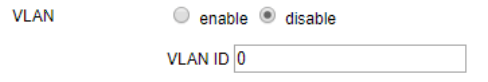
- If you need Virtual LAN support, select enable to enable VLAN and enter the VLAN ID in the field.
- In the RMCP Port field, enter the desired Remote Mail Checking Protocol (RMCP) port based on your configuration.
The default port is 623. - Once you are done completing the fields, click Save to save the CMM Network settings.
To set up CMM network via CLI:
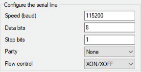
- Using a USB-to-RJ45 serial adapter, connect a management computer to the serial port on the CMM module.
- Establish a serial connection to the CMM from the management computer using a serial terminal such as Putty or Hyper Terminal, and enter the following configuration.
- Using the CMM CLI commands, set up IP addresses on the management port.
Example settings:SET IP 10.100.100.099
SET NETMASK 255.255.255.0
SET GATEWAY 10.100.100.1
SET DHCP DISABLE
APPLY SETTING
CMM CLI Commands
Description
HELPPrint help. RESETReset CMM. DEFAULTRESETReset CMM to default. VERShow CMM FW VER. PASSWORDRESETReset password. GET LAN INFOGet network info. SET IP xxx.xxx.xxx.xxxSet IP address. SET NETMASK xxx.xxx.xxx.xxxSet netmask address. SET GATEWAY xxx.xxx.xxx.xxxSet gateway address. SET MAC xx:xx:xx:xx:xx:xxSet MAC address. SET DHCP ENABLESet DHCP enable. SET DHCP DISABLESet DHCP disable. SET DHCP FAILOVERSet DHCP fails, then use manual configuration. APPLY SETTINGApply network setting. - Verify the network setup with the
GET LAN INFOcommand. - Verify that the web management utility can be accessed from a web browser.
Configure the CMM password
You can configure the CMM password via the GUI or CLI.
To change the CMM password via GUI:
- From a web browser, access the web management utility using the CMM IP address.
- Log in with the admin username and password.
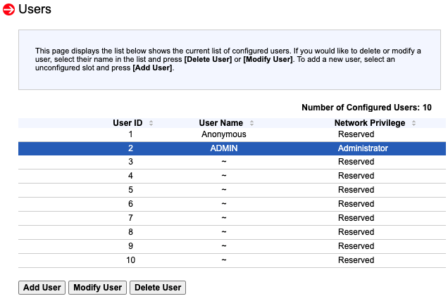
- Go to Configuration > Users.
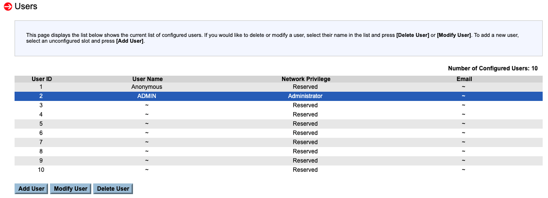
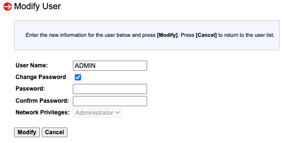
- Select the ADMIN row and click Modify User.
- Click the Change Password checkbox, change the password, and click Modify.

To reset the CMM password via CLI:
- Using a USB-to-RJ45 serial adapter, connect a management computer to the serial port on the CMM module.
- Establish a serial connection to the CMM from the management computer using a serial terminal such as Putty or Hyper Terminal.
- Use the
PASSWORDRESETcommand to reset the password to the default password.
Configure the Blade Management Network
|
|
The Blade Management Network should be in the same subnet as Chassis Management Network. See Set up the CMM network. |
To configure the Blade Management Network for a single blade:
- From a web browser, access the web management utility using the CMM IP address.
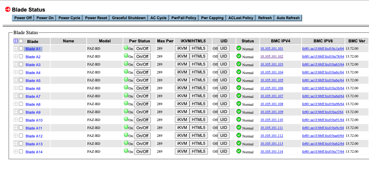
- Go to Blade System > Blade Status, and click any blade you would like to set up the Blade Management network.
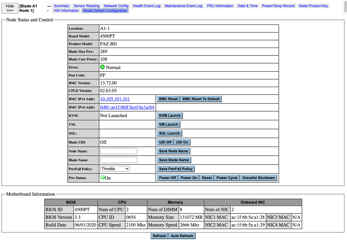
- In the Blade Configuration view, click Network Config.
- Configure the IPv4 Setting:
- Enter the IP Address, Subnet Mask, Gateway and DNS Service IP.
- Click Save.

To configure the Blade Management Network for all blades at once:
- From a web browser, access the web management utility using the CMM IP address.
- Go to Configuration > Blade IPMI Network to access the Blade IPMI Network page.

The Blade IPMI Network page enables you to modify the Blade Management Controller (BMC) networks of all your blades. - Congifure the IPV4 settings.
- Select Use the following IP address.
- From the IP Scale dropdown, select the base number each blade IP address will increase (1, 2, or 4).
- Enter the Base IP Address, Subnet Mask, Gateway, DNS Service IP, and VLAN ID.
The Base IP Address is applied to the first node of a blade’s A1 and increases by a set amount for every following node.
- Click Save and accept the warning prompts.
Remotely control blades via CMM
The CMM web management utility can perform various remote operations on the chassis, such as remote console and power control. This can be used for running diagnostic tasks on individual blades. It also allows the administrator to remotely control the FortiAnalyzer-BigData via CLIs if the Main IP and the BigData Controller IP are reset after a software hard reset.
To access the FortiAnalyzer-BigData Main CLI:
- Go to Blade System > Summary and select Blade A1.
- To enter the BMC for the FortiAnalyzer-BigData Main Host, click the BMC IPV4 link.
- Enter your username and password to log in.
The default login credentials are on the Fortinet Product Credentials card.
- Go to Remote Control > Console Redirection or iKVM/HTML5.
- Log in with username
adminand no password.
You can now configure the Main host via the CLI.
To access the Security Event Manager Controller:
- Go to Blade System > Summary and select Blade A2.
- To enter the BMC for the Security Event Manager Controller, click the BMC IPV4 link.
The default login credentials are on the Fortinet Product Credentials card. - Go to Remote Control > Console Redirection or iKVM/HTML5.
- Log in with username
rootand passwordfortinet@123.
You can now access the Security Event Manager Controller and usefazbdctlCLI commands to manage the cluster.
|
|
You can use the CMM web management utility to remotely access and control the other blades by following the general steps. You can also use the utility to remotely access the FortiAnalyzer-BigData Bootloader (see Bootloader). |
Configure the BMC password
You can configure the BMC password via the CMM.
To change the BMC password via the CMM:
- From a web browser, access the web management utility using the CMM IP address.
- Log in with the admin username and password.
- Go to Blade System > Summary.
- Select the blade you want to change, for example, Blade A1.
- To enter the BMC for the FortiAnalyzer-BigData main host, click the BMC IPV4 link.
The default login credentials are on the Fortinet Product Credentials card.
- Go to Configuration > Users.
- Select the ADMIN row and click Modify User.
- Click the Change Password checkbox, change the password, and click Modify.
To reset the BMC password via CMM:
- From a web browser, access the web management utility using the CMM IP address.
- Log in with the admin username and password.
- Go to Blade Status and select the blade you want to change, for example, Blade A1.
- Click Reset Default Configuration.
- Select the Reset Users Configuration checkbox and click Reset.
-

Turn off STP BPDU
To turn off STP BPDU:
- Connect to the Chassis Management Module
- Go to Blade System > Switch Module, and click Switch A2. The Switch Module pane opens.
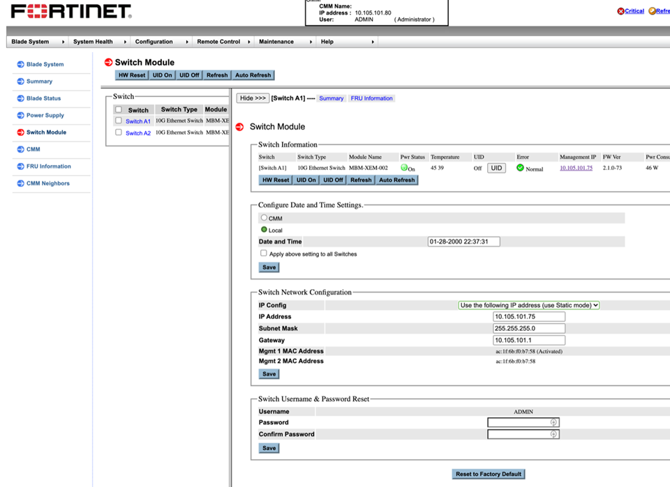

The default Username and Password are both ADMIN.
For security purposes, we recommend changing the Username and Password.
- Under Switch Network Configuration, in the IP Addess field, enter the IP address, and click Save.
- Under Switch Information, click the Management IP column, and enter the management web GUI for Switch A2.
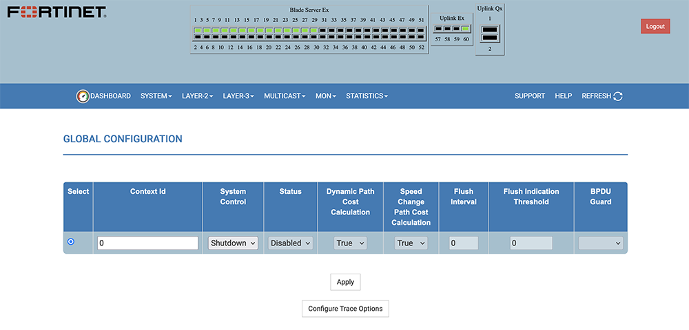
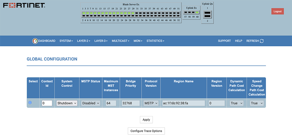
- Go to Layer-2 > MSTP > Basic Settings.
- Set MSTP Status” to Disabled .
- Set System Control to Shutdown .
- Click Apply.
- Go to Layer-2 > RSTP > Global Settings, and confirm:
Status is Disabled
System Control is Shutdown (default)