


Deploying FortiGate-VM for service chaining
FortiOS supports Nutanix service chaining to allow a service chain to direct network traffic to the FortiGate-VM for scanning. This requires the Calm and Flow features to be enabled on Nutanix, and for Prism Central to be installed on the Nutanix Acropolis hypervisor (AHV).
Nutanix service chains define a set of network function VMs (NFV) for advanced traffic processing. You can direct each defined flow in an application policy through a service chain when a chain exists. For examples, the service chain can direct network traffic on a specific port to a VM for antivirus scanning, deep packet, inspection, or packet capture. You can combine NFVs in a chain to apply multiple functions to guest VM traffic.
The following shows an example topology for this feature:

The following describes the topology in this example:
- The Nutanix AHV has Prism Central installed, with Calm and Flow enabled.
- There are three Ubuntu VMs (PC2, PC3, and PC4) installed to AHV and connected to vlan30.
- The FortiGate-VM has the following interfaces attached:
- One management interface
- Three network function chain interfaces
With this topology, you can test whether the feature is functioning by directing traffic between PC2 and PC3 through the FortiGate's virtual wire pair port2-port3 interfaces by the Nutanix service chain feature.
The following instructions describe how to configure the deployment that the topology diagram shows. Substitute the values from your own deployment where necessary.
These deployment instructions were tested using the following Nutanix platform details:
- Prism Central pc.2021.9.0.2
- Acropolis operating system 5.20.1.1
- Calm 3.3.0
- Cluster Maintenance Utilities 1.0.0.
- Epsilon 3.3.0
- Flow Security 1.0.0
- Licensing LM.2021.2.1
- NCC 4.3.0
To deploy the FortiGate-VM to the Nutanix cluster using the Calm blueprint:
- Sign in to Prism Central.
- Go to Compute & Storage > Images. Click Import Images, and upload the fortios.qcow2 image.
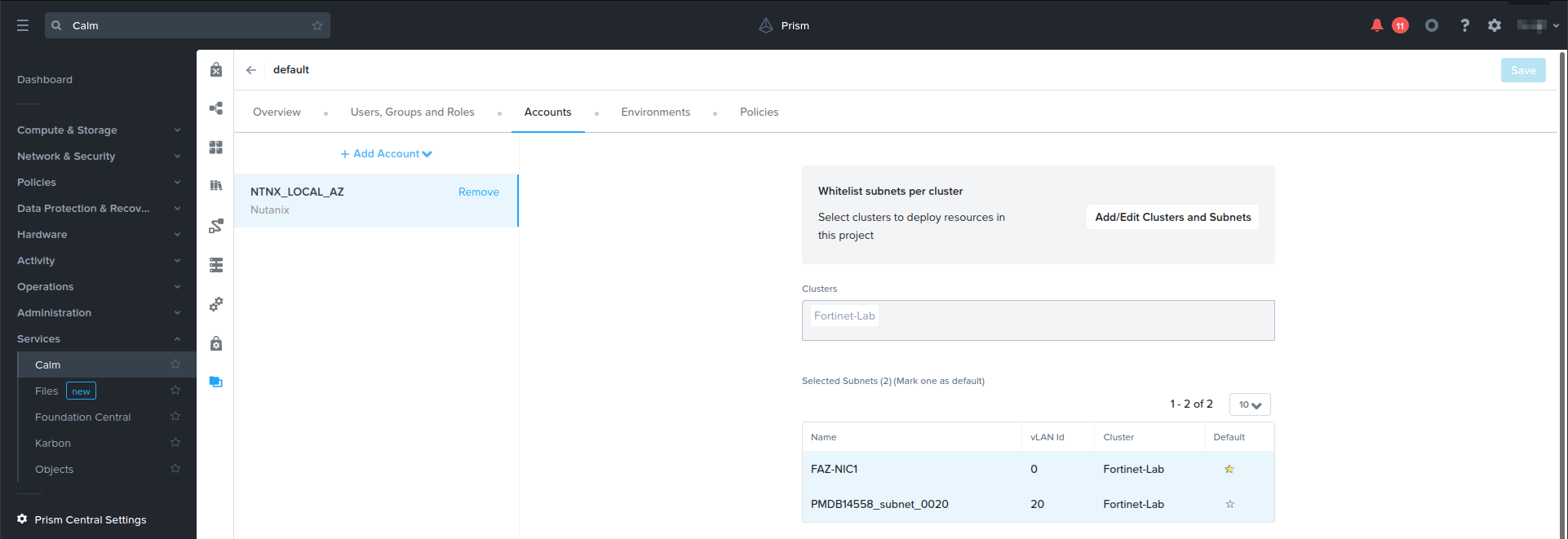
- Go to Services > Calm > Projects. Add a user account to NTNX_LOCAL_AZ, selecting a default subnet.
- Upload and configure the JSON file:
- Go to Blueprint. Upload the JSON file. In this example, it is Fortigate-Dec2021.json file.
- Go to Credentials, and set a password for the admin user. Save.
- Click the AHV application profile and configure it as follows:
- For NF_CHAIN_NAME, enter the desired chain name. In this example, it is FORTIGATE_CHAIN.
- For CLUSTER_NAME, enter the desired cluster name. In this example, it is Fortinet-Lab.
- For PC_IP, enter the PC IP address. In this example, it is 192.168.20.58.
- Click Services, Fortigate to configure the VM name, operating system image, and network adapters:
- You will use a cloud-init script to configure the FortiGate-VM. Enable Guest Customization, and select Cloud-init. Enter the desired script.
- Under Disks, from the Operation dropdown list, select Clone from Image Service.
- From the Image dropdown list, select the fortios.qcow2 image.
- Connect NIC1 to the management subnet, and add three network function chain interfaces: NIC2 for ingress, NIC2 for egress, and NIC4 for TAP.

- Click Save.
- Click Launch. In the Application Name field, enter the desired name to deploy the blueprint. In this example, it is Fortigate-BP.
- Confirm that the resources were successfully deployed:
- Go to Services > Calm > Applications, and click the application name. In this example, it is Fortigate-BP.
- On the Audit tab, check the process status. The process may take ten to fifteen minutes. If an IP not found error occurs, disregard it. You can configure the port1 static IP address later through FortGate-VM console access.
- On the Overview tab, check the application summary.
- Go to Administration > Categories. Verify that the network_function_provider FORTIGATE_CHAIN was created.
- Go to Compute & Storage > VMs. On the List tab, verify that the FortiGate-VM was deployed to AHV as NFVM. Select it, then select Launch console.
To direct traffic through the FortiGate-VM:
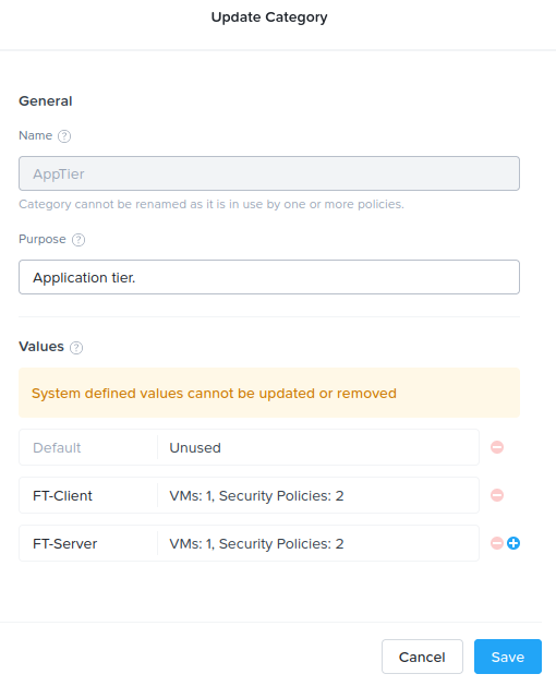
- In Prism Central, go to Categories > AppTier. Click Update. Add FT-Client and FT-Server, then save.
- Go to Categories > AppType. Click Update. Add FT_AppType, then save.
- Go to Compute & Storage > VMs. Right-click PC2. Select Manage Categories, then set the categories as follows:
- For Environment, select Testing.
- For AppType, select FT_AppType.
- For AppTier, select FT-Client.
- Go to Compute & Storage > VMs. Right-click PC3. Select Manage Categories, then set the categories as follows:
- For Environment, select Testing.
- For AppType, select FT_AppType.
- For AppTier, select FT-Server.
- Configure a security policy:
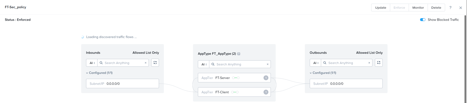
- Go to Network & Security > Security Policies. Click Create Security Policy, then click Create.
- In the Name field, enter the desired policy name. In this example, it is FT-Sec_policy.
- In the Purpose field, enter the desired purpose. In this example, it is testing.
- In the Secure This App field, select FT_AppType.
- Under Inbounds, in the Add source by: Subnet/IP field, enter 0.0.0.0/0. Click Add.
- Under Outbounds, in the Add source by: Subnet/IP field, enter 0.0.0.0/0. Click Add.
- Under AppType FT_AppType, select Set rules on App Tiers, instead. Add AppTier: FT-Client, and FT-Server.
- Configure the rules:
- For AppTier: FT-Client, create an inbound rule. In the dialog, select Redirect through a service chain, and select FORTIGATE_CHAIN. Save.

- For AppTier: FT-Server, create an inbound rule. In the dialog, select Redirect through a service chain, and select FORTIGATE_CHAIN. Save.
- For AppTier: FT-Client, create an outbound rule. In the dialog, select Redirect through a service chain, and select FORTIGATE_CHAIN. Save.
- For AppTier: FT-Server, create an outbound rule. In the dialog, select Redirect through a service chain, and select FORTIGATE_CHAIN. Save.
- For AppTier: FT-Client, create a tier-to-tier rule. In the dialog, select Redirect through a service chain, and select FORTIGATE_CHAIN. Save.
- For AppTier: FT-Server, create a tier-to-tier rule. In the dialog, select Redirect through a service chain, and select FORTIGATE_CHAIN. Save.
- For AppTier: FT-Client, create an inbound rule. In the dialog, select Redirect through a service chain, and select FORTIGATE_CHAIN. Save.
- Under Select a Policy mode, select Enforce. Click Save and Enforce.
To verify that FortiGate-VM unified threat management works:
- Verify that pings from PC3 to PC2 go through the FortiGate-VM.
- Run
diagnose sniffer packet port 3 '' 6to capture ICMP traffic with the vlan30 tag. The following shows example output for this command:
- Go to Log & Report > AntiVirus and verify that unified threat management blocks an eicar.com sample.
