
Hardware switch
A hardware switch is a virtual switch interface that groups different ports together so that the FortiGate can use the group as a single interface. Supported FortiGate models have a default hardware switch called either internal or lan. The hardware switch is supported by the chipset at the hardware level.
Ports that are connected to the same hardware switch behave like they are on the same physical switch in the same broadcast domain. Ports can be removed from a hardware switch and assigned to another switch or used as standalone interfaces.
Some of the difference between hardware and software switches are:
|
Feature |
Hardware switch |
Software switch |
|---|---|---|
|
Processing |
Packets are processed in hardware by the hardware switch controller, or SPU where applicable. |
Packets are processed in software by the CPU. |
|
STP |
Supported |
Not Supported |
|
802.1x |
Supported on the following NP6 platforms: FG-30xE, FG-40xE, and FG-110xE |
Not Supported |
|
Wireless SSIDs |
Not Supported |
Supported |
|
Intra-switch traffic |
Allowed by default. |
Allowed by default. Can be explicitly set to require a policy. |
After ports are added to a virtual switch with STP or 802.1x enabled, you can enable or disable STP or 802.1x for each member port.
To change the ports in a hardware switch in the GUI:
- Go to Network > Interface and edit the hardware switch.
- Click inside the Interface members field.
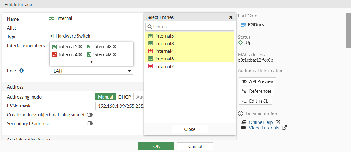
- Select interfaces to add or remove them from the hardware switch, then click Close.
To add an interface to a hardware switch, it cannot be referenced by an existing configuration and its IP address must be set to 0.0.0.0/0.0.0.0.
- Click OK.
Removed interfaces will now be listed as standalone interfaces in the Physical Interface section.
To remove ports from a hardware switch in the CLI:
config system virtual-switch
    edit "internal"
        config port
            delete internal2
            delete internal7
            ...
        end
    next
end
To add ports to a hardware switch in the CLI:
config system virtual-switch
    edit "internal"
        set physical-switch "sw0"
        config port
            edit "internal3"
            next
            edit "internal5"
            next
            edit "internal4"
            next
            edit "internal6"
            next
        end
    next
end
To add an interface to a hardware switch, it cannot be referenced by an existing configuration and its IP address must be set to 0.0.0.0/0.0.0.0.
Example of using 802.1X on virtual switches
In this example, port3 and port4 are part of a hardware switch interface. The hardware switch acts as a virtual switch so that devices can connect directly to these ports and perform 802.1X authentication on the port.
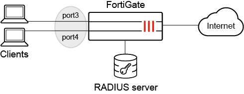
Prerequisites:
- Configure a RADIUS server (see RADIUS servers).
- Define a user group named test to use the remote RADIUS server and for 802.1X authentication (see User definition and groups).
- Configure a hardware switch (named 18188) with port3 and port4 as the members.
- Configure a firewall policy that allows traffic from the 18188 hardware switch to go to the internet.
- Enable 802.1X authentication on the client devices.
To configure 802.1X authentication on a hardware switch in the GUI:
- Go to Network > Interfaces and edit the hardware switch.
- In the Network section, enable Security mode and select 802.1X.
- Click the + to add the User group.
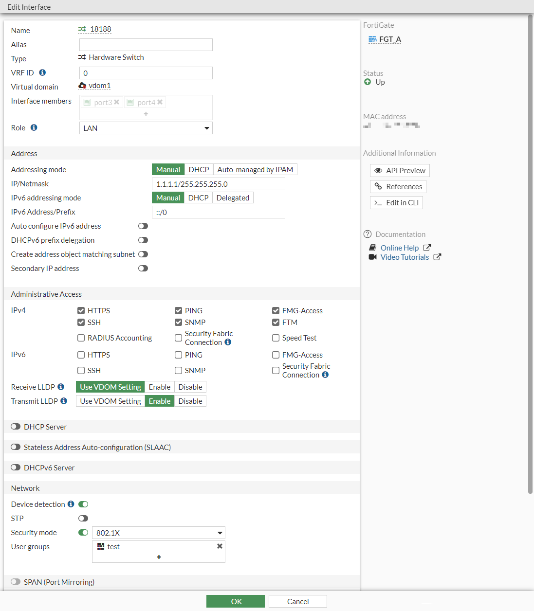
- Click OK.
To configure 802.1X authentication on a hardware switch in the CLI:
- Configure the virtual hardware switch interfaces:
config system virtual-switch edit "18188" set physical-switch "sw0" config port edit "port3" next edit "port4" next end next end - Configure 802.1X authentication:
config system interface
    edit "18188"
        set vdom "vdom1"
        set ip 1.1.1.1 255.255.255.0
        set allowaccess ping https ssh snmp fgfm ftm
        set type hard-switch
        set security-mode 802.1X
        set security-groups "test"
        set device-identification enable
        set lldp-transmission enable
        set role lan
        set snmp-index 52
    next
end
To verify the that the 802.1X authentication was successful:
- Get a client connected to port3 to authenticate to access the internet.
- In FortiOS, verify the 802.1X authentication port status:
# diagnose sys 802-1x status

Virtual switch '18188' (default mode) 802.1x member status:
  port3: Link up, 802.1X state: authorized
  port4: Link up, 802.1X state: unauthorized
Example of disabling 802.1x on one port
In this example, FortiGate is connected to two switches, and a virtual switch named hw1 is configured with two port members: port3 and port5. 802.1x authentication is enabled for port3 and disabled for port5.

To configure 802.1x authentication for individual ports:
-
Configure a virtual switch to use port3 and port5:
config system virtual-switch edit "hw1" set physical-switch "sw0" config port edit "port3" next edit "port5" next end next end -
Enable 802.1x authentication for the virtual switch:
config system interface edit "hw1" set vdom "vdom1" set ip 6.6.6.1 255.255.255.0 set allowaccess ping https ssh set type hard-switch set security-mode 802.1X set security-groups "group_radius" set device-identification enable set lldp-transmission enable set role lan set snmp-index 55 set ip-managed-by-fortiipam disable next end -
Disable 802.1x authentication on port5:
config system interface
    edit "port5"
        set vdom "vdom1"
        set type physical
        set security-8021x-member-mode disable
        set snmp-index 9
    next
end
802.1x authentication is disabled on port5 and remains enabled on port3.
Example of disabling STP on one port
In this example, FortiGate is connected to two switches, and a virtual switch named hw1 is configured with two port members: port3 and port5. STP is enabled for port3 and disabled for port5. Any STP sent to port5 is silently ignored. Port3 remains enabled for STP.

To configure STP for individual ports:
-
Configure a virtual switch to use port3 and port5:
config system virtual-switch edit "hw1" set physical-switch "sw0" config port edit "port3" next edit "port5" next end next end -
Enable STP for the virtual switch:
config system interface edit "hw1" set vdom "vdom1" set ip 6.6.6.1 255.255.255.0 set allowaccess ping https ssh set type hard-switch set stp enable set device-identification enable set lldp-transmission enable set role lan set snmp-index 55 set ip-managed-by-fortiipam disable next end -
Disable STP on port5 by enabling it as an STP edge port:
config system interface
    edit "port5"
        set vdom "vdom1"
        set type physical
        set stp-edge enable
        set snmp-index 9
    next
end
Port5 is enabled as an edge port with STP disabled. Port3 remains enabled for STP.