
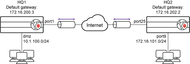
This is a sample configuration of IPsec VPN authenticating a remote FortiProxy peer with a pre-shared key.
To configure IPsec VPN authenticating a remote FortiProxy peer with a pre-shared key in the GUI:
- Configure the HQ1 FortiProxy.
- Go to VPN > IPsec Wizard and configure the following settings for VPN Setup:
- Enter a VPN name.
- For Template Type, select Site to Site.
- For Remote Device Type, select FortiProxy.
- For NAT Configuration, select No NAT Between Sites.
- Click Next.
- Configure the following settings for Authentication:
- For Remote Device, select IP Address.
- For the IP address, enter 172.16.202.1.
- For Outgoing interface, enter port1.
- For Authentication Method, select Pre-shared Key.
- In the Pre-shared Key field, enter sample as the key.
- Click Next.
- Configure the following settings for Policy & Routing:
- From the Local Interface dropdown menu, select the local interface.
- Configure the Local Subnets as 10.1.100.0.
- Configure the Remote Subnets as 172.16.101.0.
- Click Create.
- Go to VPN > IPsec Wizard and configure the following settings for VPN Setup:
- Configure the HQ2 FortiProxy.
- Go to VPN > IPsec Wizard and configure the following settings for VPN Setup:
- Enter a VPN name.
- For Template Type, select Site to Site.
- For Remote Device Type, select FortiProxy.
- For NAT Configuration, select No NAT Between Sites.
- Click Next.
- Configure the following settings for Authentication:
- For Remote Device, select IP Address.
- For the IP address, enter 172.16.2001.
- For Outgoing interface, enter port25.
- For Authentication Method, select Pre-shared Key.
- In the Pre-shared Key field, enter sample as the key.
- Click Next.
- Configure the following settings for Policy & Routing:
- From the Local Interface dropdown menu, select the local interface.
- Configure Local Subnets as 172.16.101.0.
- Configure the Remote Subnets as 10.1.100.0.
- Click Create.
- Go to VPN > IPsec Wizard and configure the following settings for VPN Setup:
To configure IPsec VPN authenticating a remote FortiProxy peer with a pre-shared key using the CLI:
- Configure the WAN interface and default route. The WAN interface is the interface connected to the ISP. The IPsec tunnel is established over the WAN interface.
- Configure HQ1.
config system interface edit "port1" set vdom "root" set ip 172.16.200.1 255.255.255.0 next end config router static edit 1 set gateway 172.16.200.3 set device "port1" next end - Configure HQ2.
config system interface
    edit "port25"
        set vdom "root"
        set ip 172.16.202.1 255.255.255.0
    next
end
config router static
    edit 1
        set gateway 172.16.202.2
        set device "port25"
    next
end
- Configure HQ1.
- Configure the internal (protected subnet) interface. The internal interface connects to the corporate internal network. Traffic from this interface routes out the IPsec VPN tunnel.
- Configure HQ1.
config system interface edit "dmz" set vdom "root" set ip 10.1.100.1 255.255.255.0 next end - Configure HQ2.
config system interface
    edit "port9"
        set vdom "root"
        set ip 172.16.101.1 255.255.255.0
    next
end
- Configure HQ1.
- Configure the IPsec phase1-interface.
- Configure HQ1.
config vpn ipsec phase1-interface edit "to_HQ2" set interface "port1" set peertype any set net-device enable set proposal aes128-sha256 aes256-sha256 aes128-sha1 aes256-sha1 set remote-gw 172.16.202.1 set psksecret sample next end - Configure HQ2.
config vpn ipsec phase1-interface
    edit "to_HQ1"
        set interface "port25"
        set peertype any
        set net-device enable
        set proposal aes128-sha256 aes256-sha256 aes128-sha1 aes256-sha1
        set remote-gw 172.16.200.1
        set psksecret  sample
    next
end
- Configure HQ1.
- Configure the IPsec phase2-interface.
- Configure HQ1.
config vpn ipsec phase2-interface edit "to_HQ2" set phase1name "to_HQ2" set proposal aes128-sha1 aes256-sha1 aes128-sha256 aes256-sha256 aes128gcm aes256gcm chacha20poly1305 set auto-negotiate enable next end - Configure HQ2.
config vpn ipsec phase2-interface
    edit "to_HQ2"
        set phase1name "to_HQ1"
        set proposal aes128-sha1 aes256-sha1 aes128-sha256 aes256-sha256 aes128gcm aes256gcm chacha20poly1305
        set auto-negotiate enable
    next
end
- Configure HQ1.
- Configure the static routes. Two static routes are added to reach the remote protected subnet. The blackhole route is important to ensure that IPsec traffic does not match the default route when the IPsec tunnel is down.
- Configure HQ1.
config router static edit 2 set dst 172.16.101.0 255.255.255.0 set device "to_HQ2" next - Configure HQ2.
config router static
    edit 2
        set dst 10.1.100.0 255.255.255.0
        set device "to_HQ1"
    next
- Configure HQ1.
- Configure two firewall policies to allow bidirectional IPsec traffic flow over the IPsec VPN tunnel.
- Configure HQ1.
config firewall policy edit 1 set name "inbound" set srcintf "to_HQ2" set dstintf "dmz" set srcaddr "172.16.101.0" set dstaddr "10.1.100.0" set action accept set schedule "always" set service "ALL" next edit 2 set name "outbound" set srcintf "dmz" set dstintf "to_HQ2" set srcaddr "10.1.100.0" set dstaddr "172.16.101.0" set action accept set schedule "always" set service "ALL" next end - Configure HQ2.
config firewall policy
    edit 1
        set name "inbound"
        set srcintf "to_HQ1"
        set dstintf "port9"
        set srcaddr "10.1.100.0"
        set dstaddr "172.16.101.0"
        set action accept
        set schedule "always"
        set service "ALL"
    next
    edit 2
        set name "outbound"
        set srcintf "port9"
        set dstintf "to_HQ1"
        set srcaddr "172.16.101.0"
        set dstaddr "10.1.100.0"
        set action accept
        set schedule "always"
        set service "ALL"
    next
end
- Configure HQ1.
- Run
diagnosecommands. Thediagnose ipsec list-sa,diagnose ipsec list-conn, anddiagnose ipsec p1-statuscommands are the key to troubleshoot why the IPsec tunnel failed to establish.