


Deployment procedures
The following deployment steps provision a FortiGate device, a FortiSwitch unit, and a FortiAP unit in the following topology:

Step 1: Bring up the FortiGate device
The following figures show the faceplate and back of the FortiGate 60F, which are similar to the FortiGate 61F:


|
|
On larger models, DMZ, HA, and MGMT ports might also be available. |
When a FortiGate device is fresh out of the box, depending on the model, there are an array of physical ports labeled according to their default configuration. To a large extent, these ports can be reconfigured, with some hardware-dependent exceptions, to serve any purpose. However, in this case, as is best in most cases, you can use the preconfigured and labeled defaults. Make a special note if you have ports labeled ‘A’ and ‘B’. If so, these are preconfigured for FortiLink and will be connected to the FortiSwitch unit.
The following table lists some of the default settings on an out-of-the-box FortiGate device.
|
Setting |
Value |
|---|---|
|
Management IP address and login credentials |
|
|
Management IP |
192.168.1.99/24 |
|
User name |
admin |
|
Password |
<blank> |
|
Ports and interfaces |
|
|
MGMT port address range (if it exists) |
192.168.1.0/24, with the FortiGate device as the default gateway |
|
LAN port only |
If there is no MGMT port, the LAN port address range is 192.168.1.0/24. |
|
MGMT and LAN port |
If there is an MGMT port, the LAN ports default to a different subnet. |
|
WAN1 |
DHCP client (will request an IP address from the ISP) |
|
LAN ports labeled ‘A’ and ‘B’ |
Preconfigured for FortiLink |
|
Firewall policies |
|
|
LAN → WAN |
A firewall policy allows outgoing traffic from LAN ports but does not allow incoming traffic from the Internet/uplink (WAN1). |
|
|
If MGMT is a separate port, it will not have default Internet access. |
See FortiGate Best Practices for tips on securing your administrative access.
Power on the FortiGate device and log in
-
Plug in the FortiGate device and power it on.
-
Plug the ISP uplink into the FortiGate WAN1 port.
-
Connect a management station to the MGMT (or LAN port 1) port using the Ethernet cable.
The management station should get an IP address from the FortiGate device. If it does not, configure the management station to 192.168.1.110/255.255.255.0 with a gateway of 192.168.1.99.
-
Open a web browser and connect to 192.168.1.99.
-
At the login page, enter the user name
admin, leave the password blank, and pressEnter.
-
You will be prompted for a new password. Choose anything that fits your password policy. Leave the Old Password field blank.

-
The first boot sequence setup continues with a FortiGate setup screen. This document skips these details.
A station that is Ethernet-connected to a FortiGate LAN port can now access the Internet through the FortiGate firewall.
Step 2: Configure FortiLink and authorize the FortiSwitch unit
FortiLink allows a FortiSwitch unit to be fully managed from the FortiGate device as if it was simply part of the FortiGate device. VLAN tags are provisioned automatically, and there is no need to configure trunks—the FortiGate device and FortiSwitch unit act as a unified device.
Remove the ports in the LAN hardware switch interface
On FortiGate models where there are no dedicated FortiLink ports like port A and port B, you need to remove two of the LAN ports from the LAN interface to be used in the FortiLink interface.
By default, LAN ports are grouped together into the LAN hardware switch interface. These ports are connected with an internal hardware switch controller and are part of the same broadcast domain.
The following steps show the configurations on a FortiGate 61F:
-
Go to Network > Interfaces and double-click on LAN.
-
In the Interface Members field, remove two physical ports by clicking on the ‘X’s.
A common practice is to use the two highest-numbered ports, but you can remove any two ports.
-
Click OK.
-
On the Network > Interfaces page, the two ports are now removed from the LAN interface, and these interfaces are listed under the Physical Interface grouping.
Configure the FortiLink interface
FortiLink connects switches (and access points) directly to the FortiGate device so that the network acts as a single device.
-
Go to Network > Interfaces.
-
Double-click on FortiLink.
-
Check if there are interface members listed at the top.
-
If there are already two members, FortiLink is ready to connect to a switch. The two members are likely the ports labeled ‘A’ and ‘B’ if they exist on your physical FortiGate device.
-
If there are no interface members, select the two LAN ports that were removed in Remove the ports in the LAN hardware switch interface.
-
-
Check the FortiLink settings.
-
In the Address section, leave the addressing mode at the default setting, Dedicated to FortiSwitch.
-
In the Address section, ensure that Automatically authorize devices is enabled.
Devices can be manually admitted one at a time later if you prefer.
-
In the Address section, disable FortiLink split interface.
The split interface is used when more than one switch is connected directly to a FortiGate device.
-
Make certain that the DHCP server is enabled.
Connected FortiSwitch units will receive an IP address in this range.

-
-
Click OK.
Make the switch controller and WiFi controller visible in the GUI
Ensure that the switch controller is visible in the GUI by changing the feature visibility.
-
Go to System > Feature Visibility.
-
Under Core Features, enable Switch Controller if it is not already enabled.
-
Under Core Features, enable WiFi Controller if it is not already enabled.
Connect the FortiLink ports to the switch ports
-
Unpack the FortiSwitch unit and deploy it.
-
Turn on the FortiSwitch unit.
-
Connect the FortiSwitch unit to the FortiGate device using two Ethernet connections. Use the two designated FortiLink ports of the FortiGate device to connect to the last two ports on the FortiSwitch unit.
It will take a few minutes for the switch to become visible and configurable in the FortiGate device.
Explore the switch controller
Go to WiFi & Switch Controller > FortiLink Interface.
This is the same FortiLink interface that you configured earlier, but there are some additional options here such as FortiOS network address control (NAC).
Check the switch authorization and topology
-
Go to WiFi & Switch Controller > Managed FortiSwitch.
-
Check that the FortiSwitch unit is visible, connected to the FortiGate device, and authorized.
If the FortiSwitch unit has not been automatically authorized, click on the icon and authorize the switch.

-
To get a topology view, use the dropdown menu in the upper right corner to change List to Topology.
The Topology view shows the logical connection between the FortiGate device and the connected FortiSwitch unit.
-
Hover over the switch icon to see the context menu with several options.
-
The following figure shows that the FortiSwitch unit is now connected, authorized, and ready to be configured.

Step 3: Create and assign VLANs in the switch controller
Create FortiSwitch VLANs
There are several predefined VLANs for NAC purposes, which allow devices connected to the FortiSwitch unit to be assigned a default VLAN automatically. This is covered in a later section. For now, you can create two example VLANs.
Up to this point, the recommended configuration has been virtually identical to this guide. At this point, you might want your specific deployment to deviate from this guide due to a preferred IP address scheme and the number of VLANs needed, and if inter-VLAN routing is needed. The following configuration is for two internal VLANs, both with Internet access and routing between them allowed.
-
Go to WiFi & Switch Controller > FortiSwitch VLANs.
-
Click Create New.
-
Assign a VLAN name. For example, enter
VLAN100. -
By default, Type is set to VLAN, and Interface is set to fortilink.
-
Assign a number between 2 and 4,094 not already in use for the VLAN ID. For example, enter
100.The default configuration uses 4089-4093 for the predefined VLANs.
-
Select a color if you want to.
-
From the Role dropdown list, select LAN.
-
For the addressing mode, click Manual.
-
In the IP/Netmask field, enter an IP address and netmask. For example, enter
10.10.100.1/255.255.255.0. -
Enable Create address object matching subnet if it is not already enabled.
This setting will be useful in policies later.

-
Enable DHCP Server.
-
Accept the default address range or adjust it for your environment.
-
Check that Same as Interface IP and Same as System DNS are enabled.

-
Click OK.
-
For the second VLAN, repeat the preceding procedure with a different interface address:
-
Enter
VLAN200for the VLAN name. -
Enter
200for the VLAN ID. -
Enter
10.10.200.1/255.255.255.0for the IP address and netmask. -
Configure other settings as needed.
-
-
Click OK.
Create firewall policies for Internet access
The Internet access policies will mirror the LAN internet policy described in Step 1: Bring up the FortiGate device.
- Go to Policy & Objects > Firewall Policy.
- Click Create New.
- Configure the firewall policy according to your VLAN names.
- Enter a name for the Internet access policy for the first VLAN. For example, enter
VLAN100-Internet. - Select your first VLAN for the incoming interface. For example, select VLAN100.
- Select WAN1 for the outgoing interface.
- Select all for the source.
- Select all for the destination.
- Select always for the schedule.
- Select all for the service.
- Click ACCEPT for the action.
- Enter a name for the Internet access policy for the first VLAN. For example, enter
- Under Firewall/Network Options, make certain that NAT is enabled and Use Outgoing Interface Address is selected.

- Accept the rest of the default settings and then click OK.
- Repeat steps 1-5 for your second VLAN.
Enable inter-VLAN routing (if needed)
Both VLANs now have Internet access. If the VLANs need to reach each other, you need to configure two more policies for inter-VLAN routing. Repeat the steps in Create firewall policies for Internet access but with changes to the incoming and outgoing interfaces.
For example, for the first inter-VLAN routing policy:
-
Select VLAN100 as the incoming interface.
-
Select VLAN200 as the outgoing interface.
For example, for the second inter-VLAN routing policy:
-
Select VLAN200 as the incoming interface.
-
Select VLAN100 as the outgoing interface.

Assign VLANs to switch ports
Now that the VLANs and policies are configured, you need to assign the VLANs to the switch ports. This method assigns VLANs statically to a port. The next section describes how to use NAC policies to assign VLANs.
-
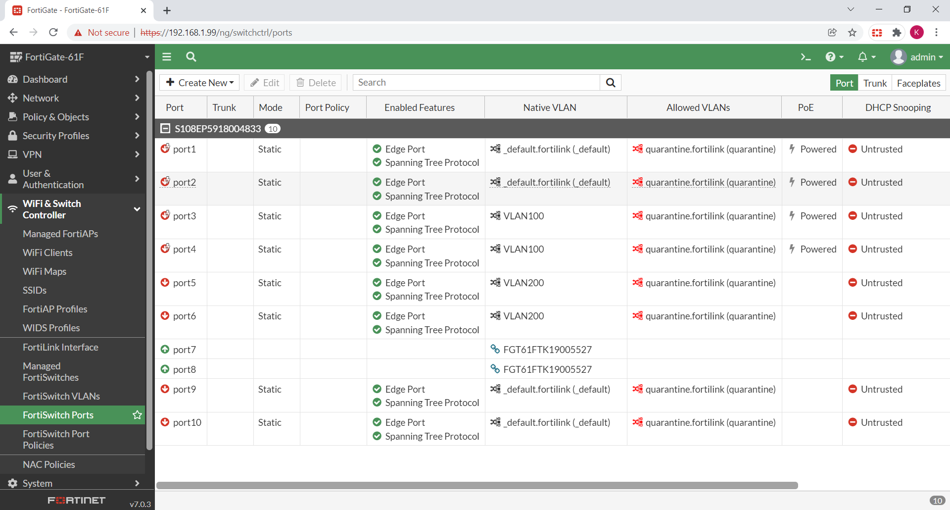
Go to WiFi & Switch Controller > FortiSwitch Ports.
-
Notice that the FortiLink ports show the FortiGate device itself in the native VLAN column. You do not need to configure a trunk port.
- To change the VLAN assigned to any port, hover over the current native VLAN of that port, and a pencil icon is displayed.
- Click the pencil icon to edit the port.
- In the Select Entries pane, select the VLAN to assign to this port.
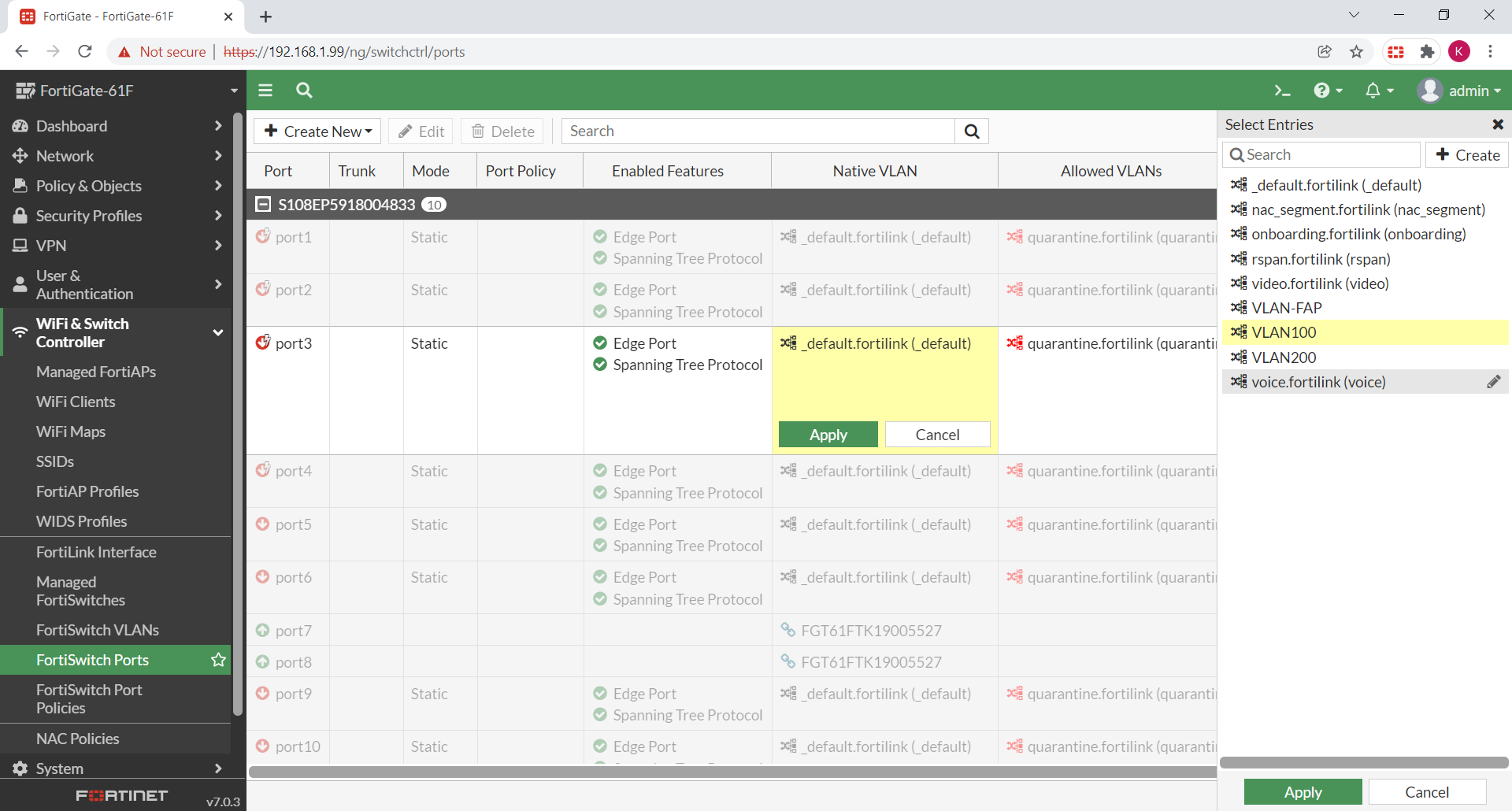
If that VLAN has not been defined yet, click Create to create a new VLAN.
Click Apply to save the change.
- In the Select Entries pane, select the VLAN to assign to this port.
- Assign other ports to static VLANs as needed.
Step 4: Set up NAC and create NAC policies
NAC identifies a device by some criteria, such as the operating system and hardware vendor, and then assigns it to a policy-defined VLAN.
By default, there is an onboarding VLAN for NAC onboarding devices. For NAC, the onboarding VLAN is treated differently than other VLANs. When a device connects to a switch port in NAC mode, the device goes the following process:
-
The device gets a DHCP address on the onboarding VLAN.
-
The device gets categorized by a NAC policy.
-
The device gets a new DHCP address on the assigned VLAN.
If the device does not match any category, the device remains in the onboarding VLAN. Therefore, consider applying stricter restrictions on the policy to allow traffic for the onboarding VLAN.
By default, there are other default defined VLANs that you can use for your NAC policies. You can also add additional VLANs for your NAC policy.
Change the onboarding VLAN
By default, FortiGate NAC policies place onboarding devices into the onboarding VLAN. To change this behavior, you can edit the VLAN from NAC Policies > FortiSwitch VLANs and edit the FortiLink interface.

Set up NAC policies on the FortiSwitch unit
You can define additional rules to assign devices into VLANs based on device patterns, user information, or EMS tags.
-
Go to WiFi & Switch Controller > NAC Policies.
-
Click Create New to created a FortiSwitch NAC policy.
-
Enter
dev-NACfor the name of the NAC policy. -
Click Enabled for the status.
-
Click Device for the category.
-
Enable MAC address and then enter a device MAC address using the
00:00:00:00:00:00format. -
You can enable multiple criteria.
-
Under Switch Controller Action, enable Assign VLAN and then select a previously configured VLAN from the dropdown list.

-
-
Click OK to save the NAC policy
-
Create other NAC policies to assign devices to different VLANs.
Assign ports to use a NAC policy
So far, you have statically assigned ports to a VLAN. However, for ports that require different access or security levels based on the device connected, they can be configured to use NAC policies.
-
Go to WiFi & Switch Controller > FortiSwitch Ports.
-
Select the ports that need to be changed to NAC mode.
-
Right-click and select Mode > NAC.

-
After applying the NAC mode, refresh the page in a few seconds. The Native VLAN value will be updated.

FortiSwitch configuration complete
Your FortiSwitch configuration is now complete. Connecting devices to ports in static mode allows traffic to pass through the firewall policy assigned to those VLANs. Connecting devices to the NAC-mode port places the device in the VLAN based on the NAC policy that matches.
Step 5: Deploy WiFi
This deployment guide does not cover the details of installing access points (APs); see the FortiAP Quick Start Guides. However, here are some of the best practices to follow:
-
Access points with integrated/internal antennas are intended for ceiling mounts. If wall mounting is necessary, use an external antenna access point with the appropriate antenna.
-
All antennas have a directional element. Omnidirectional antennas propagate the signal in a donut pattern (a torus) and have the strongest signal at the level of the access point. They work fine for 10-20-foot ceilings. Down-pointed directional antennas might be better for higher ceilings. High-gain omnidirectional antennas are a poor choice for high ceilings because they flatten the donut into a pancake, raising signal strength at the ceiling level.
-
Wall-mounted access points must have external antennas so that the signal can be directed properly. Omnidirectional antennas (the standard “rubber ducks”) need to be vertically aligned.
-
-
Be sure you have the correct power over Ethernet (PoE) level to power the access points available from the switch and that the total PoE budget is sufficient for the total number of access points.
-
Note the MAC address and/or a serial number of the access points and their locations. These notes will help with later documentation.
-
When running cable for access points, leave plenty of extra cable at the AP end to allow the access point to be moved to adjust coverage. Sometimes a few feet (meters) can eliminate an unanticipated dead spot.
Add an AP VLAN
Prepare an AP VLAN by going to WiFi & Switch Controller > FortiSwitch VLANs and creating a VLAN (see Create FortiSwitch VLANs) for AP management (control plane). This VLAN creates security isolation between the AP management (control channel) and user traffic (data channel).
-
Enter a name for the VLAN.
-
Assign a VLAN ID.
-
Select Manual for the addressing mode and assign a VLAN/gateway IP address.
-
Under Administrative Access, click Security Fabric Connection. Add other access types as needed.

-
Enable DHCP server and enter the IP address range.
-
Under Network, enable Device detection.
-
Enable Automatically authorize devices.
Even in a high-security environment, it is usually best to enable this option until the initial deployment is done. Then disable it to lock down the network.

-
Click OK.
Assign the AP VLAN to AP ports on the FortiSwitch unit
Any FortiAP units connected to the FortiSwitch ports that are assigned as the AP VLAN will automatically connect to the FortiGate device, get an IP address, and be authorized by the FortiGate device. To simplify the deployment, a FortiAP unit can connect to a FortiSwitch PoE port for power. Otherwise, an external power source is needed.
-
Go to WiFi & Switch Controller > FortiSwitch Ports.
-
Select a PoE-capable port if possible and change the native VLAN to the AP VLAN.

-
Connect the access points with Ethernet cables to the correct ports on the PoE-capable FortiSwitch unit and give them a few minutes to start and become authorized.
You can check the progress by going to Security Fabric > Physical Topology or in WiFi & Switch Controller > Managed FortiAPs.
-
Go to WiFi & Switch Controller > Managed FortiAPs.
-
If necessary, change the view in the dropdown list from Group to AP.

-
If necessary, access points that have not been automatically authorized can be authorized using the right-click menu or the Edit button.
-
Fortinet recommends using the edit function to rename the access points to something helpful, such as “Main-Lobby” or “breakroom.”
Create SSIDs
-
Go to WiFi & Switch Controller > SSIDs.
-
Click Create New > SSID.
-
Enter a name for the SSID.
This is an internal name and does not have to match an over-the-air SSID.
-
Make certain that Tunnel is selected for the traffic mode.
In tunnel mode, WLANs are treated as interfaces in the FortiGate device and behave as a VLAN interface.
-
Assign an IP address (VLAN gateway) and set up the DHCP server.

-
Under WiFi Settings, configure the following:
-
Enter the name of the SSID.
This is the over-the-air name.
-
Select WPA3 SAE or WPA2 Personal for the security mode.
Ideally, as you refine your security policies, you will use one of the enterprise security modes. See the primary documentation for how to set up WPA2 Enterprise and WPA3 Enterprise with a RADIUS server.
-
Enter a pre-shared key.

-
Click OK.
-
The SSIDs are deployed to the APs. More complex deployments involving groups of access points with different WLANs can be configured. See the primary documentation.
Configure the firewall policies
Firewall policies must be configured (see Create firewall policies for Internet access) to allow wireless access from the SSID. Here you can also define the profiles to use for scanning the traffic.

Deployment complete
The basic LAN edge network design is configured. The FortiGate device is a gateway to the Internet, a FortiSwitch unit is connected and communicating over a FortiLink, Wi-Fi is available, and an example NAC policy is configured.
You can refer to other Fortinet documentation to further secure, refine, optimize, and scale your solution.