


Deployment procedures
This section covers the following deployment examples:
Example 1: Basic FortiLink-over-VXLAN setup
The following example is a FortiLink-over-VXLAN setup. In this example, the ALAXALA switch is used as a router between the FortiGate device and the FortiSwitch unit. All packets of the control path and data path are VXLAN encapsulated and go through the ALAXALA switch.
NOTE: If you do not have an ALAXALA switch (available only in Japan at this point), any layer-3 switch or router can be used if the requirements are met.
At this point, you need to use the CLI for most of the configuration of FortiLink over VXLAN on both the FortiSwitch unit and FortiGate device. In addition, the ALAXALA switch just supports CLI configuration.
After the VXLAN tunnel is established between the FortiGate device and the FortiSwitch unit, the FortiSwitch unit will be discovered by the FortiGate device, just like in a FortiLink-over-layer-2 network. After you have authorized the FortiSwitch unit, you can manage the FortiSwitch unit over VXLAN. For example, you can configure FortiSwitch VLANs using the GUI.

For more information, refer to Managing FortiSwitch units on VXLAN interfaces as well.
Configure the FortiSwitch unit for FortiLink over VXLAN
The following example shows how to configure FortiLink over VXLAN on the FortiSwitch unit:
-
Configure a VLAN to use as the underlay for VXLAN.
config system interface
edit "vlan-1000"
set ip 10.105.21.146 255.255.255.240
set allowaccess ping https ssh
set vlanid 1000
set interface "internal"
next
end
-
Configure a static route to the underlay IPv4 address of the FortiGate device.
config router static
edit 1
set device "vlan-1000"
set dst 10.105.21.65 255.255.255.255
set gateway 10.105.21.145
next
end
-
Configure the switch trunk to make it static and disable the automatic VLAN provisioning.
NOTE:
port24is connected to the ALAXALA switch as a router.config switch trunk
edit "vxlan-underlay"
set auto-isl 1
set static-isl enable
set static-isl-auto-vlan disable
set members "port24"
next
end
-
Configure the underlay interface. The native VLAN matches the VLAN used for the underlay for the VXLAN defined in step 1 (Configure a VLAN to use as the underlay for VXLAN.).
config switch interface
edit "vxlan-underlay"
set native-vlan 1000
next
end
-
Assign VLAN ID 4094 to the “internal” interface that will be used to establish the FortiLink connection with the FortiGate device over VXLAN.
config switch interface
edit "internal"
set native-vlan 4094
next
end
-
To use a hardware-based VXLAN, you need to configure two trunks. They are
tr1andtr2in this example. Each trunk is assigned one physical link,port25andport26in this example. They should be connected to each other by a physical loopback cable. -
Create and configure trunk
tr1.config switch trunk
edit "tr1"
set auto-isl 1
set static-isl enable
set static-isl-auto-vlan disable
set members "port25"
next
end
-
Configure the
tr1interface with a native VLAN of 4087 and disable STP.config switch interface
edit "tr1"
set native-vlan 4087
set stp-state disabled
next
end
-
Create and configure trunk
tr2. Leave the rest of the values at the defaults.config switch trunk
edit "tr2"
set auto-isl 1
set static-isl enable
set static-isl-auto-vlan disable
set members "port26"
next
end
-
In the configuration for the
tr2interface, theset allowed-vlans 1-4094command means that all VLANs are FortiSwitch VLANs and that they are VXLAN encapsulated and forwarded to the FortiGate device.config switch interface
edit "tr2"
set native-vlan 4094
set allowed-vlans 1-4094
next
end
-
Configure the VXLAN interface with
tr1as the tunnel-loopback interface.-
The
vniis used for VXLAN encapsulation. -
The
remote-ippoints to the FortiGate device.
config system vxlan
edit "vx-4094"
set vni 123456
set interface "vlan-1000"
set tunnel-loopback "tr1"
set remote-ip "10.105.21.65"
next
end
-
Configure the FortiGate device for FortiLink over VXLAN
-
Configure the system interface connected to the ALAXALA switch, which is the router (gateway) toward the FortiSwitch unit.
config system interface
edit "port1"
set vdom "root"
set ip 10.105.21.65 255.255.255.240
set allowaccess ping https ssh http
next
end
-
Configure the VXLAN interface. The
vnishould be same value as on the FortiSwitch unit. Theremote-ippoints to the underlay IPv4 address of FortiSwitch unit.config system vxlan
edit "flk-vxlan"
set interface "port1"
set vni 123456
set remote-ip "10.105.21.146"
next
end
-
Enable FortiLink on the
vxlaninterface created in step 2 and set the IPv4 address. The underlined commands are automatically configured.config system interface
edit "flk-vxlan"
set vdom "root"
set fortilink enable
set ip 10.105.21.1 255.255.255.240
set allowaccess ping fabric
set type vxlan
set lldp-reception enable
set lldp-transmission enable
set interface "port1"
next
end
-
Configure a static route toward the FortiSwitch unit.
config router static
edit 0
set dst 10.105.21.128 255.255.255.192
set gateway 10.105.21.66
set device "port1"
next
end
-
Configure the DHCP server to provide the switch-controller IPv4 address to the FortiSwitch unit. DNS and NTP services are provided by the FortiGate device.
config system dhcp server
edit 0
set dns-service local
set ntp-service local
set default-gateway 10.105.21.1
set netmask 255.255.255.240
set interface "flk-vxlan"
config ip-range
edit 1
set start-ip 10.105.21.2
set end-ip 10.105.21.14
next
end
set vci-match enable
set vci-string "FortiSwitch"
next
end
Configure the ALAXALA switch as a router
The gigabitethernet 1/0/29 is connected to the FortiGate device. The gigabitethernet 1/0/28 is connected to the FortiSwitch unit managed by FortiLink over VXLAN.
system mtu 9216
interface gigabitethernet 1/0/28
mtu 9216
switchport mode access
switchport access vlan 40
interface gigabitethernet 1/0/29
mtu 9216
switchport mode access
switchport access vlan 10
interface vlan 40
ip address 10.105.21.145 255.255.255.240
ip mtu 9216
interface vlan 10
ip address 10.105.21.66 255.255.255.240
ip mtu 9216
Example 2: Add multiple VLANs to the deployment
Example 2 is a variant of Example 1. When you finish configuring the FortiSwitch unit, FortiGate device, and router, the VXLAN tunnel is established between the FortiSwitch unit and FortiGate device through the router., and then FortiLink over VXLAN becomes operational. After this point, you can configure this setup with the GUI just the same as FortiLink over layer 2. For example, after the FortiSwitch unit is managed by FortiLink over VXLAN from the FortiGate device, you can configure FortiSwitch VLANs with the GUI. No CLI configuration is required. After you add multiple FortiSwitch VLANs, the three hosts can communicate with each other through FortiLink over VXLAN and the FortiGate device. You need to configure policies on the FortiGate device to allow this traffic.

Example 3: Add multiple FortiSwitch units to the deployment
FortiLink over VXLAN supports up to 300 FortiSwitch units, depending on the FortiGate model.
There are two ways to add more FortiSwitch units to the deployment when using FortiLink over VXLAN.
-
Add more FortiSwitch islands (vertically). See Vertical scaling (adding FortiSwitch islands).
-
Add tier-2 members to FortiSwitch islands (horizontally). See Horizontal scaling (adding tier-2 members to a FortiSwitch island).
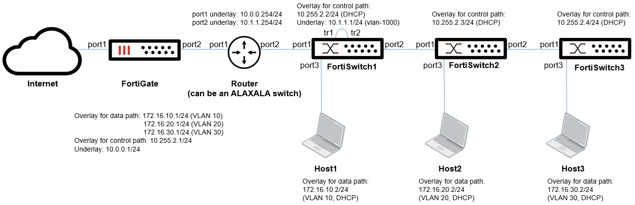
The following figure shows three FortiSwitch islands. Each FortiSwitch island contains three members.

Vertical scaling (adding FortiSwitch islands)
The following figure shows how to deploy three FortiSwitch islands.

The three hosts can communicate with each other through FortiLink over VXLAN and the FortiGate device. The VLAN for a host connected to each island should be different from the other VLANs. In this example, VLAN 10, 20, and 30 are used on the three islands, so inter-VLAN (inter-island) communication can be routed by the FortiGate device. In other words, you cannot extend the same VLAN across islands. You need to configure policies on the FortiGate device to allow inter-VLAN traffic.
To configure the FortiGate device:
You have to configure three values for remote-ip, one each for FortiSwitch1, FortiSwitch2, and FortiSwitch3.
config system vxlan
edit "flk-vxlan"
set interface "port2"
set vni 123456
set remote-ip "10.1.1.1" "10.2.2.1" "10.3.3.1"
next
end
To configure FortiSwitch1, FortiSwitch2, and FortiSwitch3:
On FortiSwitch1, FortiSwitch2 and FortiSwitch3, the VNI value should be the same; however, you need to configure unique IPv4 addresses for the underlay (10.1.1.1, 10.2.2.1, and 10.3.3.1 in this example).
config system vxlan
edit "vx-4094"
set vni 123456
set tunnel-loopback "tr1"
set interface "vlan-1000"
set remote-ip "10.0.0.1"
next
end
Horizontal scaling (adding tier-2 members to a FortiSwitch island)
The following figure shows how to deploy a single FortiSwitch island with three members.
When you add FortiSwitch2 and FortiSwitch3, there is zero-touch configuration, just like a tier-2 FortiSwitch unit connected to a tier-1 FortiSwitch unit with FortiLink over a layer-2 network. Also, physical loopback cables are not required on FortiSwitch2 and FortiSwitch3 because they do not perform VXLAN encapsulation. FortiSwitch1 performs VXLAN encapsulation for packets from FortiSwitch2 and FortiSwitch3.
After you build the Example 1 setup, you only have to connect FortiSwitch2 and FortiSwitch3 and power them up. Then FortiSwitch2 and FortiSwitch3 are managed by FortiLink over VXLAN from the FortiGate device through FortiSwitch1, and you can configure FortiSwitch2 and FortiSwitch3 using the GUI.
In this example, when you configure VLAN 10, 20, and 30 with the GUI, the three hosts can communicate with each other through FortiLink over VXLAN and the FortiGate device. You need to configure policies on the FortiGate device to allow this traffic.
Example 4: Configure NAT with FortiLink over VXLAN
VIP NAT by the FortiGate device is supported along with FortiLink over VXLAN. In the following figure, NAT and port forwarding on the FortiGate branch are used to translate the source address from 172.3.1.1 to 10.2.2.99 when packets are sent out. From the FortiGate device, the VXLAN tunnel is established with 10.2.2.99, which is translated from 172.3.1.1. On the other hand, from the FortiSwitch unit, the VXLAN tunnel is established with 10.1.1.1.

To configure the FortiGate device:
config system vxlan
edit "flk-vxlan"
set interface "port3"
set vni 123456
set remote-ip "10.2.2.99“
next
end
To configure the managed FortiSwitch unit:
config system vxlan
edit "vx-4094"
set vni 123456
set tunnel-loopback "tr1"
set interface "vlan-1000"
set remote-ip "10.1.1.1"
next
end
Example 5: Configure IPsec with FortiLink over VXLAN
To encrypt both the control path and data path, you can use Internet Protocol Security (IPsec) along with FortiLink over VXLAN. The following figure shows a FortiLink-over-VXLAN deployment with an IPsec site-to-site VPN. For FortiLink over VXLAN, the IPsec site-to-site VPN is transparent. So the VXLAN configurations are the same whether IPsec is used or not.

To configure the FortiGate device:
config system vxlan
edit "flk-vxlan"
set interface "port2"
set vni 123456
set remote-ip "10.3.3.1"
next
end
To configure the managed FortiSwitch unit:
config system vxlan
edit "vx-4094"
set vni 123456
set tunnel-loopback "tr1"
set interface "vlan-1000"
set remote-ip "10.0.0.1"
next
end