
FortiGate 1000F and 1001F fast path architecture
The FortiGate 1000F and 1001F each include one NP7 processor. All front panel data interfaces and the NP7 processor connect to the integrated switch fabric (ISF). All data traffic passes from the data interfaces through the ISF to the NP7 processor. All supported traffic passing between any two data interfaces can be offloaded by the NP7 processor. Data traffic processed by the CPU takes a dedicated data path through the ISF and the NP7 processor to the CPU.
The FortiGate 1000F and 1001F models feature the following front panel interfaces:
- One 10/100/1000/2.5GBASE-T RJ45 (HA) not connected to the NP7 processor.
- One 10/100/1000BASE-T RJ45 (MGMT) not connected to the NP7 processor.
- Eight 10G/5G/2.5G/1G/100M BASE-T RJ45 (1 to 8).
- Sixteen 10/1 GigE SFP+/SFP (9 to 24).
- Eight 25/10/1 GigE SFP28/SFP+/SFP (25 to 32), interface groups: 25 - 28, 29 - 32. Every time you change the speed of one of these interfaces from 25Gbps to 10Gbps or 1Gbps or from 10Gbps or 1Gbps to 25Gbps the speeds of the other interfaces in the group also change to that speed. When you enter the
endcommand, the CLI confirms the range of interfaces affected by the change. - Two 100/40 GigE QSFP28/QSFP+ (33 and 34). Both of these interfaces can be split into four 25/10/1 GigE SFP28 interfaces.
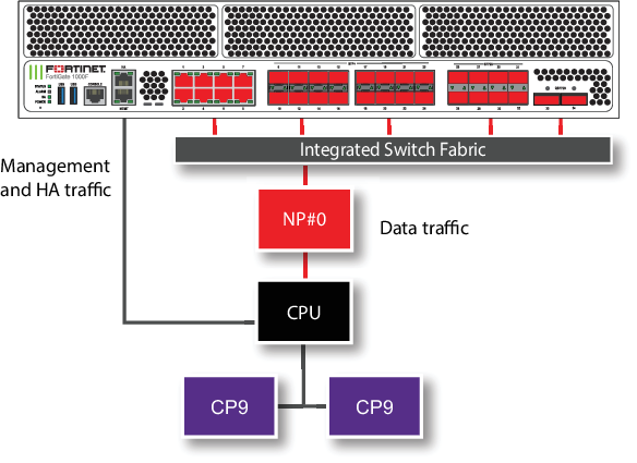
The MGMT interface is not connected to the NP7 processor. Management traffic passes to the CPU over a dedicated management path that is separate from the data path. You can also dedicate separate CPU resources for management traffic to further isolate management processing from data processing (see Improving GUI and CLI responsiveness (dedicated management CPU)).
The HA interface is also not connected to the NP7 processor. To help provide better HA stability and resiliency, HA traffic uses a dedicated physical control path that provides HA control traffic separation from data traffic processing.
The separation of management and HA traffic from data traffic keeps management and HA traffic from affecting the stability and performance of data traffic processing.
You can use the following command to display the FortiGate 1000F or 1001F NP7 configuration. The command output shows a single NP7 named NP#0 is connected to all interfaces. This interface to NP7 mapping is also shown in the diagram above.
diagnose npu np7 port-list
Front Panel Port:
Name     Max_speed(Mbps) Dflt_speed(Mbps) Sw_Trunk_Id     Sw_Tcam_Id Group_from_vdom Switch_id SW_port_id SW_port_name
-------- --------------- ---------------  --------------- ---------- --------------- --------- ---------- ------------
port1    10000           10000            8               1          0               0         58         n/a
port2    10000           10000            8               2          0               0         59         n/a
port3    10000           10000            8               3          0               0         56         n/a
port4    10000           10000            8               4          0               0         57         n/a
port5    10000           10000            8               5          0               0         54         n/a
port6    10000           10000            8               6          0               0         55         n/a
port7    10000           10000            8               7          0               0         52         n/a
port8    10000           10000            8               8          0               0         53         n/a
port9    10000           10000            8               9          0               0         51         n/a
port10   10000           10000            8               10         0               0         50         n/a
port11   10000           10000            8               11         0               0         49         n/a
port12   10000           10000            8               12         0               0         48         n/a
port13   10000           10000            8               13         0               0         35         n/a
port14   10000           10000            8               14         0               0         34         n/a
port15   10000           10000            8               15         0               0         33         n/a
port16   10000           10000            8               16         0               0         32         n/a
port17   10000           10000            8               17         0               0         31         n/a
port18   10000           10000            8               18         0               0         30         n/a
port19   10000           10000            8               19         0               0         29         n/a
port20   10000           10000            8               20         0               0         28         n/a
port21   10000           10000            8               21         0               0         27         n/a
port22   10000           10000            8               22         0               0         26         n/a
port23   10000           10000            8               23         0               0         25         n/a
port24   10000           10000            8               24         0               0         24         n/a
port25   25000           10000            8               25         0               0         23         n/a
port26   25000           10000            8               26         0               0         22         n/a
port27   25000           10000            8               27         0               0         20         n/a
port28   25000           10000            8               28         0               0         21         n/a
port29   25000           10000            8               29         0               0         19         n/a
port30   25000           10000            8               30         0               0         17         n/a
port31   25000           10000            8               31         0               0         18         n/a
port32   25000           10000            8               32         0               0         16         n/a
port33   100000          100000           8               33         0               0         12         n/a
port34   100000          100000           8               34         0               0         8          n/a
-------- --------------- ---------------  --------------- ---------- --------------- --------- ---------- ------------

Name     sw_id hash nr_link valid default sw_tid
-------- ---------------------------------------
-------- ---------------------------------------

NP Port:
Name   Switch_id SW_port_id SW_port_name
------ --------- ---------- ------------
np0_0  0         4          n/a
np0_1  0         0          n/a
------ --------- ---------- ------------
* Max_speed: Maximum speed, Dflt_speed: Default speed
* SW_port_id: Switch port ID, SW_port_name: Switch port name
The command output also shows the maximum speeds of each interface.
The NP7 processor has a bandwidth capacity of 200 Gigabits. You can see from the command output that if all interfaces were operating at their maximum bandwidth the NP7 processor would not be able to offload all the traffic.
The FortiGate-1000F and 1001F can be licensed for hyperscale firewall support, see the Hyperscale Firewall Guide.
Splitting the port33 and port34 interfaces
You can use the following command to split each FortiGate 1000F and 1001F 33 and 34 (port33 and port34) 100/40 GigE QSFP28/QSFP+ interface into four 25/10/1 GigE SFP28 interfaces. For example, to split interface 33 (port33), enter the following command:
config system global
set split-port port33
end
The FortiGate 1000F and 1001F restarts and when it starts up the port33 interface has been replaced by four SFP28 interfaces named port33/1 to port33/4.
|
|
A configuration change that causes a FortiGate to restart can disrupt the operation of an FGCP cluster. If possible, you should make this configuration change to the individual FortiGates before setting up the cluster. If the cluster is already operating, you should temporarily remove the secondary FortiGate(s) from the cluster, change the configuration of the individual FortiGates and then re-form the cluster. You can remove FortiGate(s) from a cluster using the Remove Device from HA cluster button on the System > HA GUI page. For more information, see Disconnecting a FortiGate. |
By default, the speed of each split interface is set to 10000full (10GigE). These interfaces can operate as 25GigE, 10GigE, or 1GigE interfaces depending on the transceivers and breakout cables. You can use the config system interface command to change the speeds of the split interfaces.
If you set the speed of one of the split interfaces to 25000full (25GigE), all of the interfaces are changed to operate at this speed (no restart required). If the split interfaces are set to 25000full and you change the speed of one of them to 10000full (10GigE) they are all changed to 10000full (no restart required). When the interfaces are operating at 10000full, you can change the speeds of individual interfaces to operate at 1000full (1GigE).
Configuring FortiGate 1000F and 1001F NPU port mapping
You can use the following command to configure FortiGate-1000F and 1001F NPU port mapping:
config system npu-post
config port-npu-map
edit <interface-name>
set npu-group {All-NP | NP0-link0 | NP0-link1}
end
end
end
You can use port mapping to assign data interfaces or LAGs to send traffic to selected NP7 processor links.
<interface-name> can be a physical interface or a LAG.
All-NP, (the default) distribute sessions to the LAG connected to NP0.
NP0-link0, send sessions to NP0 link 0.
NP0-link1, send sessions to NP0 link 1.
NP0-link0 NP0-link1, send sessions to both NP0 link 0 and NP0 link 1.
For example, use the following syntax to assign the FortiGate-1000F front panel 100Gigabit interface 33 to NP0-link0 and interface 34 to NP0-link 1. The resulting configuration splits traffic from the 100Gigabit interfaces between the two NP7 links:
config system npu-post
config port-npu-map
edit port33
set npu-group NP0-link0
next
edit port34
set npu-group NP0-link1
end
end
While the FortiGate-1000F or 1001F is processing traffic, you can use the diagnose npu np7 cgmac-stats <npu-id> command to show how traffic is distributed to the NP7 links.
You can use the diagnose npu np7 port-list command to see the current NPU port map configuration. For example, after making the changes described in the example, the output of the diagnose npu np7 port-list command shows different Sw_Trunk_Ids for port33 and port34 and these interfaces are listed in a port mapping summary at the bottom of the command output.