


Map Management
Map management allows you to create visual representations of your access points (APs) to accurately represent the physical layout of a site. For best results, create separate maps for each floor in multi-level buildings, and use accurate architectural drawings as a basis for your images. Crop each floor map to remove extra space and save it as a PNG, JPEG, BMP, or GIF file no larger than 2MB before adding it to FortiAIOps.
Note: Provide a unique name to the site/building/floor plan. Do not use the same name across different device groups.
To set up a working map, you'll need to complete several tasks:
-
Import a graphic map of the floor. See Importing a Map Image.
-
Add a new site to FortiAIOps. See Add a Campus, Building, and Floor to the Map.
-
Add a building.
-
Add a floor.
-
Place AP icons on the map to represent the WLAN network topology. See
Add APs, Floor APs, and Landmarks to Maps.
-
View the map. See Viewing Maps.
Importing a Map Image
Follow these steps to import a topology map:
-
Navigate to Wireless > Map Management.
-
Select a floor.
-
Click Change Image in the Floor Map section.
-
Select Image Type as Floor and Operation as Upload. Select the Image File by using the browse tab and click on Upload.
Next, add controllers and APs to the map.
Importing a Floor Map
FortiAIOps supports importing a floor map plan created on and exported from the FortiPlanner. Once the floor plan is created in the FortiPlanner, select Export in the project menu. The floor map to be imported is a .zip file.
Note:Only exported .zip files from the FortiPlanner can be imported. Contact the Customer Support to obtain the relevant version of the FortiPlanner. For more information on creating floor plans on the FortiPlanner, see the FortiPlanner User Guide.
-
Navigate to Wireless>Map Management page.
-
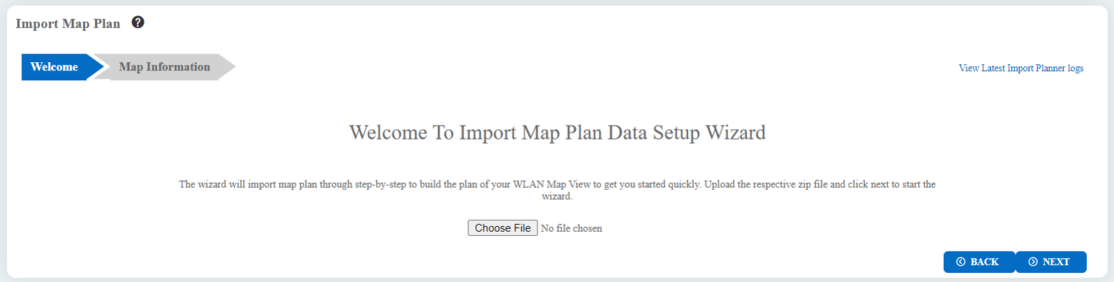
Click Import, the Import Map Plan screen is displayed.
-
Browse to the .zip file on your system and click Next. A summary of map information is displayed.
-
Map the unassigned APs and click Finish.
-
The planner for each site is displayed. On the Map Management screen, you can add and delete floors in the map and manage the APs on each floor of the site.
In case of errors importing the map, click View Latest Import Planner logs, to view the error logs.
You can perform the following operations on each floor:
- Add APs - Select the APs to be added to the floor map.
- Floor APs - Select the APs to be deleted from the floor map.
- Landmarks - Add or delete landmarks on the floor map.
- Change Image - Upload a new image or delete an existing image from the floor map.
Click Save to save changes to the map
Adding a Site, Building, and Floor to the Map
To create a new location (site, building, floor) in the enterprise, follow these steps:
-
Navigate to Wireless > Map Management page. All current maps are displayed on the Map Management page.
-
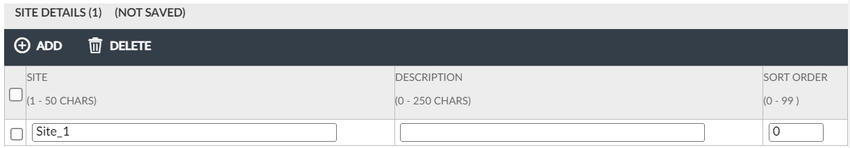
To add a new site, click on the Site Details section and then click on Add. A new site can only be added to the top level, Enterprise, which is the default.
-
Provide a name, description, and sort order for the site.
-
Click Save Changes.
-
In the left pane, double-click on the name of the new site you just created.
-
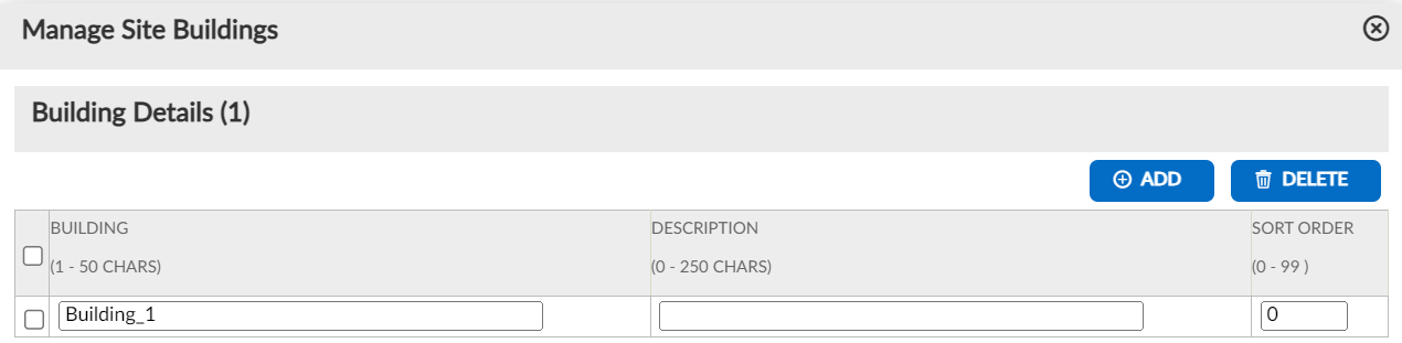
Click on the Buildings icon. In the Building Details pop-up, click Add.
-
Provide a name, description, and sort order for the building.
-
Click Save Changes.
-
In the left pane, double-click on the name of the new building you just created.
-
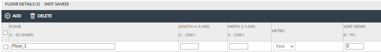
In the Floor Details section, click Add.
-
Provide a floor name, length, width, metric, and sort order for the floor.
-
Click Save Changes.
Adding APs, Floor APs, and Landmarks to Maps
To create the network map of your site, follow these steps:
-
Once a map image has been imported, add the APs to the map as close as possible to their actual physical location.
-
Select a floor by its heading in the left column to see a map of the floor. If the floor does not have a corresponding map, complete the steps to Import a Map Image.
-
Optionally, alter the map using the options Show Map and Show Scale in the Image Map section.
-
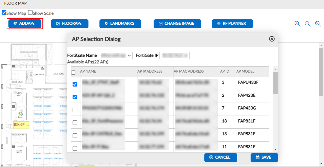
Click Add APs and select the APs to add from the drop-down list on the AP selection pop-up, then click Save. Drag the selected APs into position on the map.
-
To add landmarks to the map, click Landmarks > Add.
-
Once you have finished making changes, click Save Changes.
Editing AP Details
To edit the details of an access point (AP), follow these steps:
-
In the Map Management screen, click APs to display the AP list.
-
Select the AP you want to edit by clicking on its icon on the map or by selecting it from the AP list.
-
Click Edit to open the AP details window.
-
Edit the required fields, such as the AP name or its location coordinates.
-
Click Save to save the changes made to the AP details.
-
Click Cancel to discard any changes and close the AP details window.
Viewing Maps
You can view the placement of APs on a map or view Heat Maps that show the following five attributes of those APs:
-
Throughput
-
Loss
-
Channel Utilization
-
Number of Stations
-
Signal Strength
Heat map coloring depends on the distance between APs and selected attribute (throughput, loss, channel utilization, or stations) for all the APs on the floor. If there is only one AP on the floor, the entire floor will show the same coverage. See Heat Maps.
To view maps and heat maps, follow these steps:
-
Click on Wireless > Heat Maps.
-
Select a floor to display the map.
-
Optionally, alter the map using the options Floor Visibility or Show Heat Map.
-
To limit the map, click Select Channels, select channels, and then click Save Changes.
-
After any changes, click on the Refresh icon.
RF Planner
The RF planner is a tool that enables you to plan for new access points, areas, and obstacles (walls, shafts, etc.). It allows you to place APs and draw walls or columns in both View and Edit modes.

To use the RF planner, follow these steps:
-
Navigate to Map Management > RF Planner.
-
Add the required access points to the floor map and generate a heat map to predict the expected signal strength throughout the coverage area.
-
Adjust the placement of your APs based on the predicted signal strength and try out different placements for the APs before installing them.
-
Draw a floor plan of the coverage area and place the APs on your floor plan.
-
Run heat maps to predict the signal strength.
View Mode: In View mode, the floor map displays the coverage pattern, data rate, channel, and signal strength of the access points. You can select the 2.4GHz, 5GHz, or 6GHz frequency to view the access point details.
Edit Mode: In Edit mode, you can add or edit new access points. To do this, drag the required access point from the "Add APs" panel and place it on the floor map. Right-click on an access point and edit its configuration, such as the access point transmission power in dBm, channel, orientation, placement direction (in angles), ceiling, wall, and desk.
To draw walls and columns on the floor map, use the provided widgets. Select the required widget and draw the wall or column on the map. A column is a closed drawing with four walls, while a wall is demarcated as lines. Right-click on the created walls and columns to specify the composition or material used to construct them. Each material has a different attenuation value.