
FortiClient as dialup client
When FortiGate is configured as a dial-up VPN gateway, remote FortiClient users with dynamic IP addresses can establish secure connections over the Internet to access private resources protected by FortiGate.
This topic demonstrates using the Remote Access template on the VPN Wizard to configure FortiClient as a dialup client.
The FortiClient Secure Internet Access (SIA) template for the VPN Wizard also creates a remote access VPN with the addition of routing all Internet traffic through the FortiGate IPsec VPN tunnel for security inspection. For more information, see Configure FortiClient SIA for IPsec VPN tunnels.
Example
In this example, the FortiGate protects a local network (10.88.0.0/24) that a remote FortiClient user needs to securely access over the Internet using a VPN connection. The FortiGate is configured as a dialup VPN server on port3, and the FortiClient is the dialup IPsec VPN client.

This example uses IKE version 2 over UDP transport. For remote user authentication, a local user is configured to be a part of a local user group on the FortiGate.
Starting with FortiClient 7.4.4, IKEv1 is no longer supported on the client. IKEv1 is now considered a legacy configuration.
Also, FortiClient 7.4.4 does not support IPv6. Use FortiClient 7.4.6 or later.
For other authentication methods, see the following topics:
Some ISPs may block ESP and UDP ports. Therefore, consider using TCP as Transport.
Go to VPN > VPN Tunnels > Settings and enable Allow VPN negotiations over TCP. Once enabled, dialup VPNs will use Auto for Transport mode, allowing clients to attempt a UDP connection first before failing over to TCP.
For more details, see LDAP authentication with TCP as transport.
To configure IPsec VPN with FortiClient as the dialup client in the GUI:
-
Configure a local user:
-
Go to User & Authentication > User Definition and click Create New.
-
Set the User Type to Local User, then click Next.
-
Set the Login Credentials, then click Next:
-
Username: vpnuser1
-
Password: Enter a suitable password
-
-
Disable Two-factor Authentication, then click Next.
-
Set User Account Status to Enabled and disable User Group, then click Submit.
-
-
Configure a local user group:
-
Go to User & Authentication > User Groups and click Create New.
-
Configure the following:
Field
Value
Name
vpngroup
Type
Firewall
Members
vpnuser1
-
Click OK.
For other types of authentication, such as LDAP, PKI, or SAML, see User & Authentication.
-
-
Go to VPN > VPN Wizard.
-
Enter a name for the VPN in the Tunnel name field. In this example, remote_vpn
-
Set Select a template to Remote Access.
-
Click Begin.
-
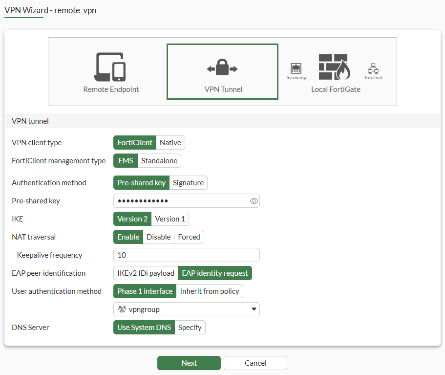
Configure the VPN tunnel settings:
Field
Value
VPN client type
FortiClient
For configuring remote access for Native clients, see:
FortiClient management type
EMS (default)
In most enterprise deployments, EMS is used to manage FortiClients and remote VPN settings. FortiClients managed this way are licensed through EMS.
In 8.0 and later, standalone FortiClients can be purchased that are directly licensed through FortiCloud and FortiIdentity Cloud.
Authentication method
Pre-shared key
Pre-shared key
Enter a suitable key.
The same pre-shared key is used by all remote users on the FortiClient to connect to the dialup VPN. For better security, use a digital certificate instead.
IKE
Version 2
NAT traversal
Enable
Set Keepalive frequency to 10.
EAP peer identification
EAP identity request
User authentication method
Phase 1 interface
Select vpngroup from the drop-down list.
Optionally, if you have multiple user groups configured, select Inherit from policy and then specify the groups. See Using single or multiple user groups for user authentication for details.
DNS Server
Use System DNS
-
Click Next.
-
Configure the Remote Endpoint settings:
Field
Value
Addressing mode for connected endpoints
Manual
IPAM is the preferred method.
Addresses to assign to connected endpoints
10.10.2.1-10.10.2.200
Subnet for connected endpoints
255.255.255.255
Security posture gateway matching Disable EMS SN verification Disable Save password
Enable
Auto Connect
Disable
Always up (keep alive)
Disable
-
Click Next.
-
Configure the Local FortiGate settings:
Field
Value
Incoming interface that binds to tunnel
WAN (port3)
Disable Create and add interface to zone.
Local interface
DMZ (port2)
Local address
DMZ_network
Click + to create a new address object with Type set to Subnet and IP/Netmask set to 10.88.0.0/24, if not already configured.
-
Click Next.
-
Review the configuration and, if everything is correct, click Submit.
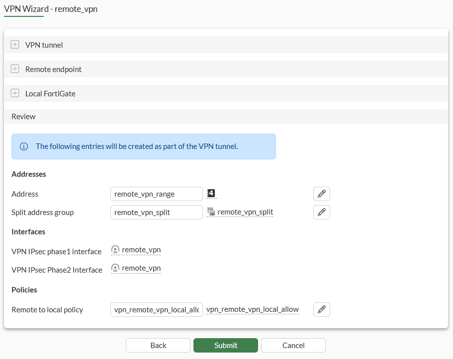
Because internet traffic is not routed through this firewall, the VPN Wizard automatically configures split tunneling. Only traffic destined for the Split address group remote_vpn_split will go through this tunnel.
To configure IPsec VPN with FortiClient as the dialup client in the CLI:
-
Configure a local user:
config user local edit "vpnuser1" set type password set passwd ****** next end -
Configure a local user group:
config user group edit "vpngroup" set member "vpnuser1" next end -
Configure the DMZ (port2) interface that connects to the corporate internal network:
config system interface edit "port2" set vdom "root" set ip 10.88.0.254 255.255.255.0 next end -
Configure the address group for split tunneling:
config firewall address
    edit "DMZ_Network"
        set subnet 10.88.0.0 255.255.255.0
    next
end
config firewall addrgrp edit "remote_vpn_split" set member "DMZ_Network" next end -
Configure the WAN interface.
The WAN interface is the interface connected to the ISP. It can be configured in static mode (as shown here), DHCP, or PPPoE mode. It is recommended to configure it with a static IP address to ensure that the IPsec VPN configuration on the on the FortiClient stays unchanged if the WAN IP changes on the FortiGate. The IPsec tunnel is established over the WAN interface.
config system interface edit "port3" set vdom "root" set ip 203.0.113.249 255.255.255.0 next end -
Configure the client address pool.
You must create a firewall address to assign an IP address to a VPN client from the address pool.
config firewall address edit "remote_vpn_range" set type iprange set start-ip 10.10.2.1 set end-ip 10.10.2.200 next end -
Configure the IPsec phase1-interface.
PSK is used as the authentication method in this example. Signature authentication is also an option.
config vpn ipsec phase1-interface edit "remote_vpn" set type dynamic set interface "port3" set ike-version 2 set peertype any set net-device disable set mode-cfg enable set proposal es128-sha256 aes256-sha256 aes128gcm-prfsha256 aes256gcm-prfsha384 chacha20poly1305-prfsha256 set dhgrp 20 21 set eap enable set eap-identity send-request set wizard-type dialup-forticlient set authusrgrp "vpngroup" set assign-ip-from name set dns-mode auto set ipv4-split-include "remote_vpn_split" set ipv4-name "remote_vpn_range" set save-password enable set psksecret ***** next end -
Configure the IPsec phase2-interface:
config vpn ipsec phase2-interface edit "remote_vpn" set phase1name "remote_vpn" set proposal aes128-sha256 aes256-sha256 aes128gcm aes256gcm chacha20poly1305 set dhgrp 20 21 next end -
Configure a firewall policy to allow client traffic flow over the IPsec VPN tunnel to the FortiGate’s lan interface:
config firewall policy
   edit 1
        set name "inbound"
        set srcintf "remote_vpn"
        set dstintf "port2"
        set action accept
        set srcaddr "remote_vpn_range"
        set dstaddr "DMZ_Network"
        set schedule "always"
        set service "ALL"
        set nat enable
    next
end
One or more user groups for user authentication can be configured under a single IPsec VPN tunnel. See Using single or multiple user groups for user authentication for details.
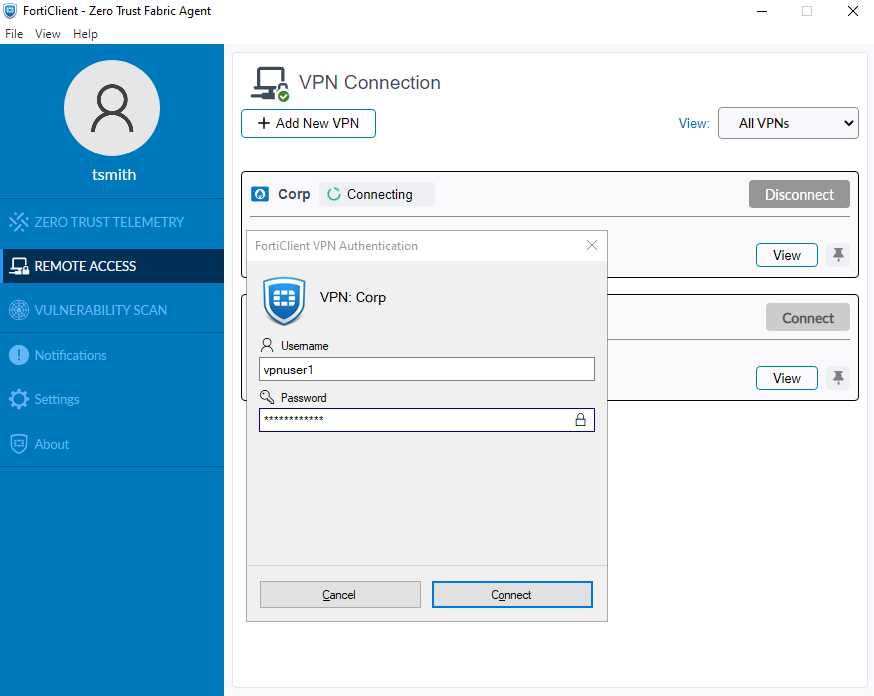
To configure a VPN directly on the FortiClient:
-
In FortiClient, go to Remote Access and click Add a new connection.
-
Set VPN to IPsec VPN and specify a Connection Name.
-
Set Remote Gateway to the FortiGate’s WAN IP address (203.0.113.249).
-
Set Authentication Method to Pre-Shared Key and enter the key.
-
Configure the remaining settings as needed, then click Save.
-
Go to the Remote Access tab, select the VPN, and then click Connect.
To establish an IPsec tunnel, the Phase 1 and Phase 2 configurations of the dial-up IPsec VPN on FortiGate must precisely match the corresponding settings on FortiClient.
To verify the tunnel status in the GUI:
-
On the FortiGate, go to Dashboard > Network Monitor > VPN.
-
Find the new tunnel, remote_vpn_0 in this example.
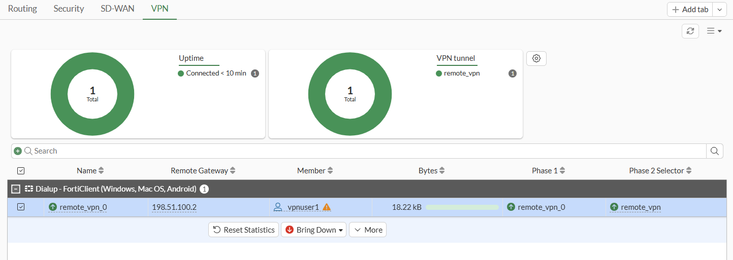
Successfully established dialup IPsec VPN tunnels are displayed using a parent name followed by an index, creating a structured and organized association with the parent tunnel. For example, the parent name remote_vpn results in tunnel names such as remote_vpn_0, remote_vpn_1, and so on.
-
Hover the cursor over the tunnel name to see additional details.
To verify the tunnel status:
-
Verify the IPsec Phase 1 tunnel status on the FortiGate, either using the CLI or the Command palette (CTRL+P) > CLI diagnostics:
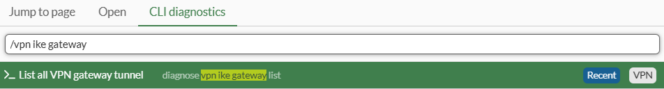
# diagnose vpn ike gateway list name remote_vpn_0

vd: root/0
name: remote_vpn_0
version: 2
interface: port3 5
addr: 203.0.113.249:4500 -> 198.51.100.2:61978
tun_id: 10.10.2.1/::10.0.0.3
remote_location: 0.0.0.0
network-id: 0
transport: UDP
created: 496s ago
eap-user: vpnuser1
2FA: no
peer-id: 198.51.100.2
peer-id-auth: no
FortiClient UID: 9A016B5A6E914B42AD4168C066EB04CA
assigned IPv4 address: 10.10.2.1/255.255.255.255
nat: me peer
pending-queue: 0
PPK: no
IKE SA: created 1/1  established 1/1  time 7880/7880/7880 ms
IPsec SA: created 1/1  established 1/1  time 20/20/20 ms

  id/spi: 21718 0fd2b81ac558640c/66ea3061dc95301d
  direction: responder
  status: established 496-488s ago = 7880ms
  proposal: aes256-sha256
  child: no
  SK_ei: e88f1ac99983dd5f-08e807aeb605a06f-ddcbde523c652452-b7bf877a8ef9020e
  SK_er: f57903b04ab2e9a2-da36555aada93571-0d0343dd4bee6e89-f69d2394c415ae6e
  SK_ai: b2a1d56be7354fa1-2d761f2f3027c3ca-ae20e2f2a322d1f2-57d878b39febe294
  SK_ar: c2448f95a13ace5d-b6aa2f93f78f6f6c-6c3af0a16d221264-bebb43fa1897938f
  PPK: no
  message-id sent/recv: 0/6
  QKD: no
  PQC-KEM (IKE): no
  PQC-KEM (all IPsec): no
  lifetime/rekey: 86400/85641
  DPD sent/recv: 00000000/00000000
  peer-id: 198.51.100.2
Note that FortiGate acts as the responder, establishes the IKEv2 VPN tunnel with remote FortiClient user with IP 198.51.100.2 over UDP NAT-T port 4500 on its port3 interface, and dynamically assigns a VPN IP of 10.10.2.1 to FortiClient endpoint. The authenticated username is also displayed in the
eap-userfield. -
Verify the IPsec Phase 2 tunnel status on the FortiGate:
# diagnose vpn tunnel list name remote_vpn_0

list all ipsec tunnel in vd 0
------------------------------------------------------
name=remote_vpn_0 ver=2 serial=8 203.0.113.249:4500->198.51.100.2:61978 nexthop=203.0.113.3 tun_id=10.10.2.1 tun_id6=::10.0.0.3 status=up dst_mtu=1500 weight=1 country=ZZ
bound_if=5 real_if=5 lgwy=static/1 tun=intf mode=dial_inst/3 encap=none options[0x23a8]=npu rgwy-chg rport-chg frag-rfc  run_state=0 role=primary accept_traffic=1 overlay_id=0

parent=remote_vpn index=0
proxyid_num=1 child_num=0 refcnt=6 ilast=1 olast=44059296 ad=/0
stat: rxp=369 txp=0 rxb=29687 txb=0
dpd: mode=on-demand on=1 status=ok idle=20000ms retry=3 count=0 seqno=0
natt: mode=keepalive draft=0 interval=10 remote_port=61978
fec: egress=0 ingress=0
proxyid=remote_vpn proto=0 sa=1 ref=2 serial=1 add-route
  src: 0:0.0.0.0-255.255.255.255:0
  dst: 0:10.10.2.1-10.10.2.1:0
  SA:  ref=3 options=20682 type=00 soft=0 mtu=1422 expire=42480/0B replaywin=2048
       seqno=1 esn=0 replaywin_lastseq=00000171 qat=0 rekey=0 hash_search_len=1
  life: type=01 bytes=0/0 timeout=43189/43200
  dec: spi=4237d1be esp=aes key=32 28080aad5adb7d3c766c5be609c355e2a8be09d4f80793be7cd2aa0291d5a5a5
       ah=sha256 key=32 77e0869053c451223f138ba2f8b9f53b6a319cd13e1486de90f5b3b86be62715
  enc: spi=476588dc esp=aes key=32 87a2d4ff73c053e5f8c528a14ec12914fb5f7f5f3737f8b6db70f28f4aef7047
       ah=sha256 key=32 73cfdadc0fdf96b844d67d9a49f30944043134be7e14dd054fca7295cf32c194
  dec:pkts/bytes=369/29687, enc:pkts/bytes=0/0
  npu_flag=00 npu_rgwy=0.0.0.0:0 npu_lgwy=0.0.0.0:0 npu_selid=0
  dec_npuid=0 enc_npuid=0 dec_engid=-1 enc_engid=-1 dec_saidx=-1 enc_saidx=-1
Note the decryption, encryption, and authentication keys negotiated in Phase 2 to protect subnets under the src and dst fields. FortiOS also automatically adds the dynamically assigned VPN IP of 10.10.2.1 to its traffic selectors for dialup tunnel remote_vpn_0.
To verify traffic through the IPsec tunnel:
-
1. On the remote FortiClient user, initiate ICMP traffic to a machine in the 10.88.0.0/24 network and verify that traffic goes through:
# ping 10.88.0.7
Pinging 10.88.0.7 with 32 bytes of data:
Reply from 10.88.0.7: bytes=32 time=2ms TTL=63
Reply from 10.88.0.7: bytes=32 time=2ms TTL=63
-
On FortiGate, run a sniffer trace for ICMP packets destined to 10.88.0.7:
# diagnose sniffer packet any 'host 10.88.0.7' 4 0 l
Using Original Sniffing Mode
interfaces=[any]
filters=[host 10.88.0.7]
2026-04-13 12:08:17.297621 remote_vpn in 10.10.2.1 -> 10.88.0.7: icmp: echo request
2026-04-13 12:08:17.297733 port2 out 10.88.0.254 -> 10.88.0.7: icmp: echo request
2026-04-13 12:08:17.298459 port2 in 10.88.0.7 -> 10.88.0.254: icmp: echo reply
2026-04-13 12:08:17.298487 remote_vpn out 10.88.0.7 -> 10.10.2.1: icmp: echo reply
The ICMP request packets are received on remote_vpn_0 tunnel interface and routed to the port2 interface. ICMP reply packets are received on the port2 interface and routed back out on remote_vpn_0 tunnel interface.
For more information, see Performing a sniffer trace or packet capture.
-
Optionally, run real time IKE debug using appropriate filters for troubleshooting if the IPsec tunnel does not come up:
# diagnose vpn ike log filter rem-addr4 198.51.100.2
# diagnose debug application ike -1
# diagnose debug enable
For more information, see VPN IPsec troubleshooting.