


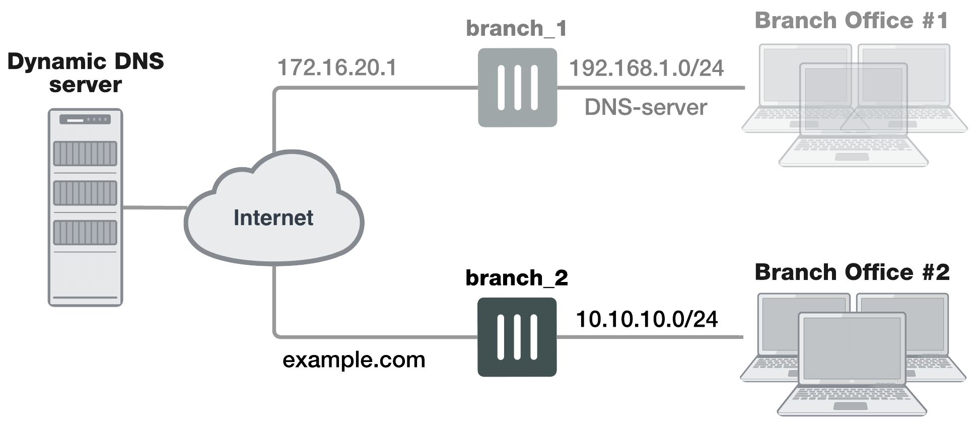
Configuration overview
When a FortiGate unit receives a connection request from a remote VPN peer, it uses IPsec Phase 1 parameters to establish a secure connection and authenticate the VPN peer. Then, if the security policy permits the connection, the FortiGate unit establishes the tunnel using IPsec Phase 2 parameters and applies the security policy. Key management, authentication, and security services are negotiated dynamically through the IKE protocol.
To support these functions, the following general configuration steps must be performed:
- Configure the branch_2 FortiGate unit with the dynamic IP address. This unit uses a Local ID string instead of an IP address to identify itself to the remote peer. See Configuring the dynamically-addressed VPN peer, which is made up of configuring branch_2's VPN tunnel settings and security policies.
- Configure the fixed-address VPN peer. To initiate a VPN tunnel with the dynamically-addressed peer, this unit must first retrieve the IP address for the domain from the dynamic DNS service. See Configuring the fixed-address VPN peer, which is made up of configuring branch_1's VPN tunnel settings and security policies.
Configuring the dynamically-addressed VPN peer
It is assumed that this FortiGate unit (branch_2) has already had its public facing interface, for example the wan1, configured with the proper dynamic DNS configuration.
Configuring branch_2, the dynamic address side
Define the Phase 1 parameters needed to establish a secure connection with the remote peer. See Phase 1 parameters. During this procedure you need to choose if you will be using route-based or policy-based VPNs.
- Go to VPN > IPsec Tunnels and create the new custom tunnel or edit an existing tunnel.
- Edit Network (full configuration options are only available once you click the Convert To Custom Tunnel button).
- Enter the following information:
- Edit Authentication and complete the following:
- Edit Phase 1 Proposal and complete the following:
- Open the Phase 2 Selectors panel.
Define the Phase 2 parameters needed to create a VPN tunnel with the remote peer. For details on Phase 2, see Phase 2 parameters. - Enter the following information and select OK.
|
Remote Gateway |
Select Static IP Address. The remote peer this FortiGate is connecting to has a static IP public address. If the remote interface is PPPoE do not select Retrieve default gateway from server. |
|
IP Address |
Enter |
|
Interface |
Select the Internet-facing interface wan1 (selected by default). |
|
NAT Traversal |
Select Enable (selected by default). |
|
Keepalive Frequency |
Enter a keepalive frequency (In seconds; set to 10 by default). |
|
Dead Peer Detection |
Select a dead peer detection option. On Idle will attempt to reestablish VPN tunnels when a connection becomes idle (the idle interval is not a negotiated value). |
|
Mode |
Select Aggressive. |
|
Local ID |
Enter A character string used by the This value must be identical to the value in the This peer ID field of the Phase 1 remote gateway configuration on the branch_1 remote peer. |
|
Name |
Automatically entered as the name of the VPN tunnel. |
|
Phase 1 |
Select The name of the Phase 1 configuration that you defined earlier. |
Define security policies to permit communications between the private networks through the VPN tunnel. Route-based and policy-based VPNs require different security policies. For detailed information about creating security policies, see Defining VPN security policies.
After defining the two address ranges, select one of Creating branch_2 route-based security policies or Creating branch_2 policy-based security policies to configure the appropriate VPN policies.
Define VPN connection names for the address ranges of the private networks. These addresses are used in the security policies that permit communication between the networks. For more information, see Defining VPN security policies.
Define an address name for the IP address and netmask of the private network behind the local FortiGate unit.
- Go to Policy & Objects > Addresses.
- Select Create New.
- Enter the following information, and select OK.
- Select Create New.
- Enter the following information, and select OK.
|
Name |
Enter |
|
Type |
Select IP/Netmask. |
|
Subnet / IP Range |
Enter Include the netmask or specify a specific range. |
|
Interface |
Select internal. The interface that will be handling the traffic from the internal network. |
Define an address name for the IP address and netmask of the private network behind the remote peer.
|
Name |
Enter |
|
Type |
Select IP/Netmask. |
|
Subnet / IP Range |
Enter Include the netmask. Optionally you can specify a range |
|
Interface |
Select any. The interface that will be handling the remote VPN traffic on this FortiGate unit. If you are unsure, or multiple interfaces may be handling this traffic use |
Creating branch_2 route-based security policies
Define ACCEPT security policies to permit communication between the branch_2 and branch_1 private networks. Once the route-based policy is configured a routing entry must be configured to route traffic over the VPN interface.
Define a policy to permit the branch_2 local FortiGate unit to initiate a VPN session with the branch_1 VPN peer.
- Go to Policy & Objects > IPv4 Policy and select Create New.
- Enter the following information, and select OK.
- Select Create New.
- Enter the following information, and select OK.
- Optionally configure any other security policy settings you require such as UTM or traffic shaping for this policy.
- Place these policies in the policy list above any other policies having similar source and destination addresses. This will ensure VPN traffic is matched against the VPN policies before any other policies.
|
Name |
Enter an appropriate name for the policy. |
|
Incoming Interface |
Select internal. The interface that connects to the private network behind this FortiGate unit. |
|
Outgoing Interface |
Select branch_2. The VPN Tunnel (IPsec Interface). |
|
Source |
Select branch_2_internal. Select the address name for the private network behind this FortiGate unit. |
|
Destination Address |
Select branch_1_internal. The address name the private network behind the remote peer. |
|
Action |
Select ACCEPT. |
|
NAT |
Disable NAT. |
|
Comments |
Route-based: Initiate a branch_2 to branch_1 VPN tunnel. |
Define a policy to permit the branch_1 remote VPN peer to initiate VPN sessions.
|
Name |
Enter an appropriate name for the policy. |
|
Incoming Interface |
Select branch_2. The VPN Tunnel (IPsec Interface). |
|
Outgoing Interface |
Select internal. The interface connecting the private network behind this FortiGate unit. |
|
Source |
Select branch_1_internal. The address name for the private network behind the remote peer. |
|
Destination Address |
Select branch_2_internal. The address name for the private network behind this FortiGate unit. |
|
Action |
Select ACCEPT. |
|
NAT |
Disable NAT. |
|
Comments |
Route-based: Initiate a branch_1 to branch_2 internal VPN tunnel. |
Creating routing entry for VPN interface - CLI
config router static
edit 5
set dst 0.0.0.0 0.0.0.0
set dynamic-gateway enable
set device wan1
next
end
This routing entry must be added in the CLI because the dynamic-gateway option is not available in the GUI.
Creating branch_2 policy-based security policies
Define an IPsec policy to permit VPN sessions between the private networks. Define an IPsec policy to permit the VPN sessions between the local branch_2 unit and the remote branch_1 unit.
- Go to Policy & Objects > IPv4 Policy and select Create New.
- Enter the following information, and select OK.
- Optionally configure any other security policy settings you require such as UTM or traffic shaping for this policy.
- Place these policies in the policy list above any other policies having similar source and destination addresses. This will ensure VPN traffic is matched against the VPN policies before any other policies.
|
Name |
Enter an appropriate name for the policy. |
|
Incoming Interface |
Select internal. The interface connecting the private network behind this FortiGate unit. |
|
Outgoing Interface |
Select wan1. The FortiGate unit’s public interface. |
|
Source |
Select branch_2_internal. The address name for the private network behind this local FortiGate unit. |
|
Destination Address |
Select branch_1_internal. The address name for the private network behind branch_1, the remote peer. |
|
Action |
Select IPsec. Under VPN Tunnel, select branch_2 from the drop-down list. The name of the Phase 1 tunnel. Select Allow traffic to be initiated from the remote site. |
|
Comments |
Policy-based: allows traffic in either direction to initiate the VPN tunnel. |
Configuring the fixed-address VPN peer
The fixed-address VPN peer, branch_1, needs to retrieve the IP address from the dynamic DNS service to initiate communication with the dynamically-addressed peer, branch_2. It also depends on the peer ID (local ID) to initiate the VPN tunnel with branch_2.

Define the Phase 1 parameters needed to establish a secure connection with the remote peer. For more information, see Phase 1 parameters.
- Go to VPN > IPsec Tunnels and create the new custom tunnel or edit an existing tunnel.
- Edit Network (if it is not available, you may need to click the Convert to Custom Tunnel button).
- Enter the following information and select OK.
- Edit Authentication, enter the following information and select OK.
- Define the Phase 2 parameters needed to create a VPN tunnel with the remote peer. See Phase 2 parameters. Enter these settings in particular:
|
Remote Gateway |
Select Dynamic DNS. The remote peer this FortiGate is connecting to has a dynamic IP address. |
|
Dynamic DNS |
Type the fully qualified domain name of the remote peer (for example, |
|
Interface |
Select wan1. The public facing interface on the fixed-address FortiGate unit. |
|
Mode Config |
Select Aggressive. |
|
Peer Options |
Select This peer ID, and enter |
|
Peer Options |
Select This peer ID, and enter |
|
Name |
Enter |
|
Phase 1 |
Select branch_1. |
The branch_1 FortiGate unit has a fixed IP address and will be connecting to the branch_2 FortiGate unit that has a dynamic IP address and a domain name of example.com. Remember if you are using route-based security policies that you must add a route for the VPN traffic.
Defining address ranges for branch_1 security policies
As with branch_2 previously, branch_1 needs address ranges defined as well. See Defining policy addresses.
- Go to Policy & Objects > Addresses and select Create New > Address.
- Enter the following information, and select OK.
- Define an address name for the IP address and netmask of the private network behind the remote peer.
- Create another address. Enter the following information, and select OK.
|
Name |
Enter |
|
Type |
Select IP/Netmask. |
|
Subnet / IP Range |
Enter |
|
Interface |
Select internal. This is the interface on this FortiGate unit that will be handling with this traffic. |
|
Name |
Enter |
|
Type |
Select IP/Netmask. |
|
Subnet / IP Range |
Enter |
|
Interface |
Select any. The interface on this FortiGate unit that will be handling with this traffic. If you are unsure, or multiple interfaces may be handling this traffic use |
Creating branch_1 route-based security policies
Define an ACCEPT security policy to permit communications between the source and destination addresses. See Defining VPN security policies.
- Go to Policy & Objects > IPv4 Policy and select Create New.
- Enter the following information, and select OK.
- Select Create New.
- Enter the following information, and select OK.
|
Name |
Enter an appropriate name for the policy. |
|
Incoming Interface |
Select internal. The interface that connects to the private network behind the |
|
Outgoing Interface |
Select branch_1. The VPN Tunnel (IPsec Interface) you configured earlier. |
|
Source |
Select branch_1_internal. The address name that you defined for the private network behind this FortiGate unit. |
|
Destination Address |
Select branch_2_internal. The address name that you defined for the private network behind the |
|
Action |
Select ACCEPT. |
|
NAT |
Disable NAT. |
|
Comments |
Internal -> branch2 |
To permit the remote client to initiate communication, you need to define a security policy for communication in that direction.
|
Name |
Enter an appropriate name for the policy. |
|
Incoming Interface |
Select branch_1. The VPN Tunnel (IPsec Interface) you configured earlier. |
|
Outgoing Interface |
Select internal. The interface that connects to the private network behind this FortiGate unit. |
|
Source |
Select branch_2_internal. The address name that you defined for the private network behind the |
|
Destination Address |
Select branch_1_internal. The address name that you defined for the private network behind this FortiGate unit. |
|
Action |
Select ACCEPT. |
|
NAT |
Disable NAT. |
|
Comments |
branch_2 -> Internal |
Creating branch_1 policy-based security policies
A policy-based security policy allows you the flexibility to allow inbound or outbound traffic or both through this single policy.
This policy-based IPsec VPN security policy allows both inbound and outbound traffic
- Go to Policy & Objects > IPv4 Policy and select Create New.
- Enter the following information, and select OK.
- Place this security policy in the policy list above any other policies having similar source and destination addresses.
|
Incoming Interface |
Select internal. The interface that connects to the private network behind this FortiGate unit. |
|
Outgoing Interface |
Select wan1. The FortiGate unit’s public interface. |
|
Source |
Select branch_1_internal. The address name that you defined for the private network behind this FortiGate unit. |
|
Destination Address |
Select branch_2_internal. The address name that you defined for the private network behind the remote peer. |
|
Action |
Select IPsec. Under VPN Tunnel, select branch_1 from the drop-down list. The name of the Phase 1 tunnel. Select Allow traffic to be initiated from the remote site. |
Results
Once both ends are configured, you can test the VPN tunnel.
To test the VPN initiated by branch_2
- On branch_2, go to Monitor > IPsec Monitor.
All IPsec VPN tunnels will be listed on this page, no matter if they are connected or disconnected. - Select the tunnel listed for branch_2, and select the status column for that entry.
The status will say Bring Up and remote port, incoming and outgoing data will all be zero. This indicates an inactive tunnel. When you right-click and select Bring Up, the FortiGate will try to set up a VPN session over this tunnel. If it is successful, Bring Up will change to Active, and the arrow icon will change to a green up arrow icon. - If this does not create a VPN tunnel with increasing values for incoming and outgoing data, you need to start troubleshooting:
To test the VPN initiated by branch_1
- On branch_1, go to Monitor > IPsec Monitor.
- Select the tunnel listed for branch_1, and select the status column.
The difference between branch_2 and branch_1 at this point is that the tunnel entry for branch-1 will not have a remote gateway IP address. It will be resolved when the VPN tunnel is started. - If this does not create a VPN tunnel with increasing values for incoming and outgoing data, you need to start troubleshooting.
Some troubleshooting ideas include:
- If there was no entry for the tunnel on the monitor page, check the Auto Key (IKE) page to verify the Phase 1 and Phase 2 entries exist.
- Check the security policy or policies, and ensure there is an outgoing policy as a minimum.
- Check that you entered a local ID in the Phase 1 configuration, and that branch_1 has the same local ID.
- Ensure the local DNS server has an up-to-date DNS entry for example.com.
For more information, see Troubleshooting.